Filters, Receivers, Transmitters and Transceivers

A filter and microstrip filtering technology, applied in the field of communication, can solve the problems of large volume, low power, and difficulty in reaching the average power of the cavity

Active Publication Date: 2016-03-09
XFUSION DIGITAL TECH CO LTD
View PDF3 Cites 0 Cited by
  • Summary
  • Abstract
  • Description
  • Claims
  • Application Information

AI Technical Summary

Problems solved by technology

For metal cavity filters, the metal cavity has good high power characteristics and insertion loss, but its huge size poses a huge challenge to the competitiveness of next-generation products
There are many types of non-metal cavity filters. Although the volume is small, the power is low. For example, the integrated dielectric filter has a power of only 10~50W, and the SAW filter is below 1W.
Suspended microstrip filters have appeared in recent years. Since the power capacity of microstrip filters is limited by factors such as the temperature resistance of the plate, the width and thickness of the copper skin, it can only reach about 80W at present, and it is difficult to reach the average power of the cavity. 100W or more required

Method used


Image

  • Filters, Receivers, Transmitters and Transceivers
  • Filters, Receivers, Transmitters and Transceivers
  • Filters, Receivers, Transmitters and Transceivers

Examples


Embodiment Construction

[0027] The following will clearly and completely describe the technical solutions in the embodiments of the present invention with reference to the drawings in the embodiments of the present invention. Obviously, the described embodiments are part of the embodiments of the present invention, not all of them. Based on the embodiments of the present invention, all other embodiments obtained by persons of ordinary skill in the art without making creative efforts shall fall within the protection scope of the present invention.

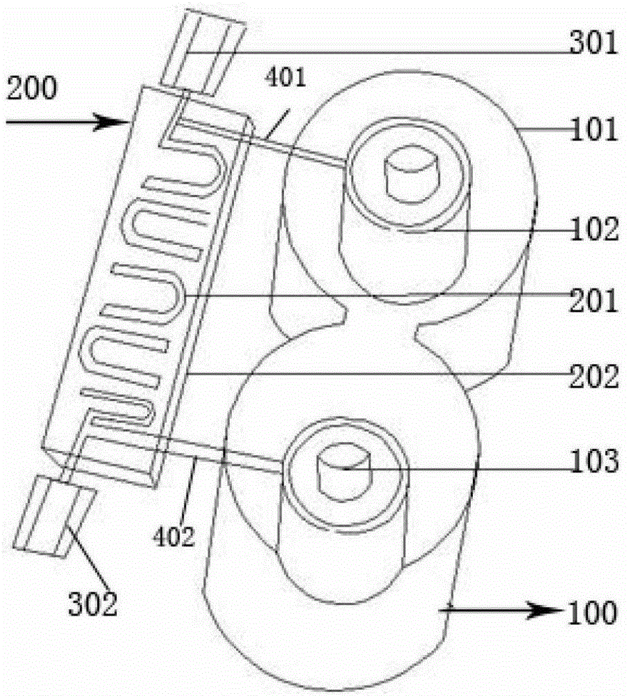
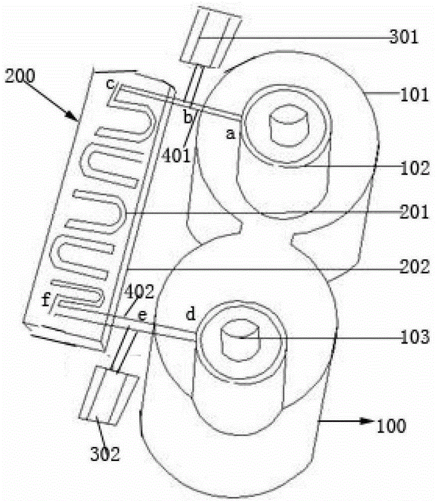
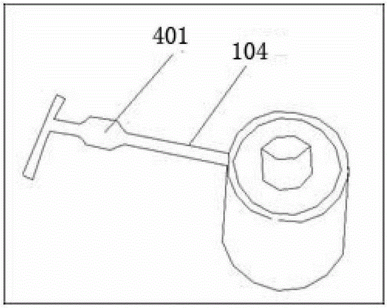
[0028] figure 1 is a schematic structural diagram of a filter according to an embodiment of the present invention. Such as figure 1 As shown, the filter may include: a resonant cavity assembly 100, a microstrip filter assembly 200 and connectors 401, 402, wherein the resonant cavity assembly 100 includes at least two resonant cavities 101 connected in parallel, and each resonant cavity 101 is provided with a resonator 102 and a tuning screw 103, the micr...


PUM


Abstract

Embodiments of the present invention provide a filter, a receiver, a transmitter, and a transceiver. The filter includes a resonant cavity component, a microstrip filtering component, and two connecting pieces, where the resonant cavity component includes at least two resonant cavities connected in parallel, each resonant cavity is provided with a resonator and a tuning screw, the microstrip filtering component includes a dielectric substrate and a microstrip positioned on the dielectric substrate, one of the connecting pieces matches and connects one end of the microstrip to the resonator on one resonant cavity, the other connecting piece matches and connects the other end of the microstrip to the resonator on another resonant cavity, and impedance of the resonant cavity component is less than impedance of the microstrip filtering component. The filter, receiver, transmitter, and transceiver in the embodiments of the present invention not only achieve minimization of the total size but also ensure the power capacity index.

Description

technical field [0001] The present invention relates to the field of communication, and more particularly, to a filter, receiver, transmitter and transceiver. Background technique [0002] The duplexer of the base station transceiver module is composed of a radio frequency (Radio Frequency, referred to as "RF") cavity filter, which is generally located on the back structure of the transceiver single board, and is used for single-channel high-power signal transmission, including transmitting channel filter and receive channel filter. [0003] With the development of multi-carrier and multi-standard mobile communications, the demand for miniaturization of radio frequency modules tends to be strong. There are metal cavity filters (commonly known as coaxial cavity filters) and non-metal cavity filters. For metal cavity filters, the metal cavity has good high-power characteristics and insertion loss, but its huge size poses a huge challenge to the competitiveness of next-generat...

Claims


Application Information

Patent Timeline
Patent Type & Authority Patents(China)
IPC IPC(8): H01P1/20H01P1/203H01P1/208
CPCH01P1/2053H01P1/20309H01P1/2084
Inventor 周彦昭
Owner XFUSION DIGITAL TECH CO LTD
Why Eureka
Try Eureka