
A method of manufacturing a semiconductor device

A manufacturing method and semiconductor technology, applied in semiconductor/solid-state device manufacturing, electrical components, circuits, etc., can solve problems such as etching loading, immature technology, complexity, etc., to improve performance, ensure critical dimensions, and avoid size reduction Effect

Active Publication Date: 2017-02-22
SEMICON MFG INT (SHANGHAI) CORP
View PDF5 Cites 0 Cited by
  • Summary
  • Abstract
  • Description
  • Claims
  • Application Information

AI Technical Summary

Problems solved by technology

[0004] Although in the prior art, there are already some improvement schemes for the above problems, such as using BARC, DBARC (developer-soluble bottom anti-reflective coating), TARC, etc. under the photoresist used to form the ion implantation masking layer, and applying OPC (Optical Proximity Correction, Optical Proximity Correction), etc. However, there are certain problems in these solutions, such as high cost and etching loading problems in the application of BARC technology, DBARC technology is not yet mature, and TARC has no effect on improving the CD uniformity of semiconductor substrates. No help, and the technology of applying OPC technology to semiconductor substrates is not mature and the process is relatively complicated, etc.
[0005] Therefore, it is necessary to propose a new manufacturing method for semiconductor devices to solve the above-mentioned problem that the reflected light below the ion implantation shielding layer affects the critical dimensions of the ion implantation shielding layer, and improve the performance of semiconductor devices

Method used


Image

  • A method of manufacturing a semiconductor device
  • A method of manufacturing a semiconductor device
  • A method of manufacturing a semiconductor device

Examples


Embodiment Construction

[0035] In the following description, numerous specific details are given in order to provide a more thorough understanding of the present invention. It will be apparent, however, to one skilled in the art that the present invention may be practiced without one or more of these details. In other examples, some technical features known in the art are not described in order to avoid confusion with the present invention.

[0036] It should be understood that the invention can be embodied in different forms and should not be construed as limited to the embodiments set forth herein. Rather, these embodiments are provided so that this disclosure will be thorough and complete, and will fully convey the scope of the invention to those skilled in the art. In the drawings, the proportional relationship of components (layers, regions, etc.) does not represent the actual size and proportion of each component; the size and relative size of layers and regions may be exaggerated for clarity....


PUM


Abstract

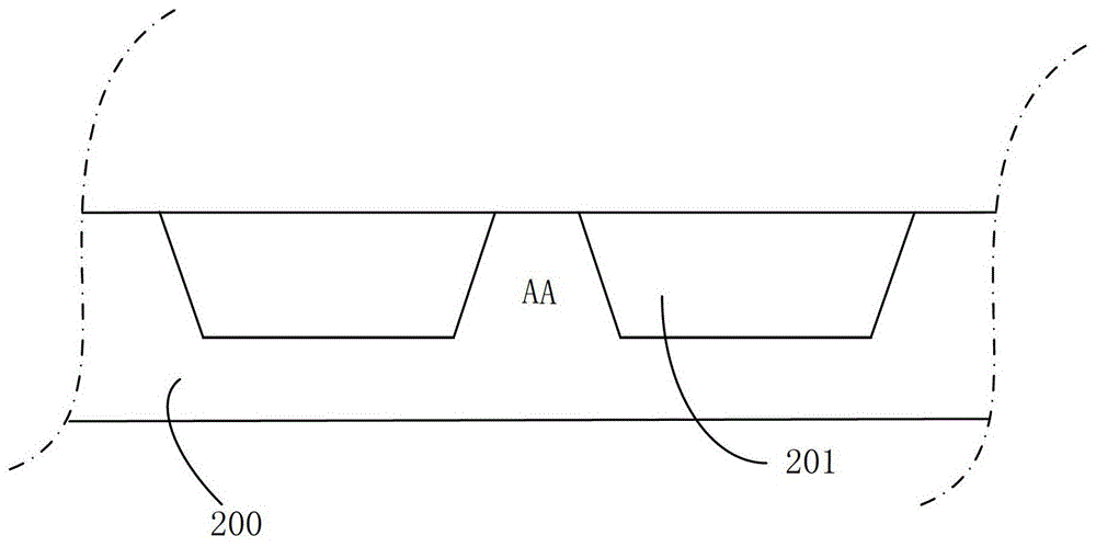
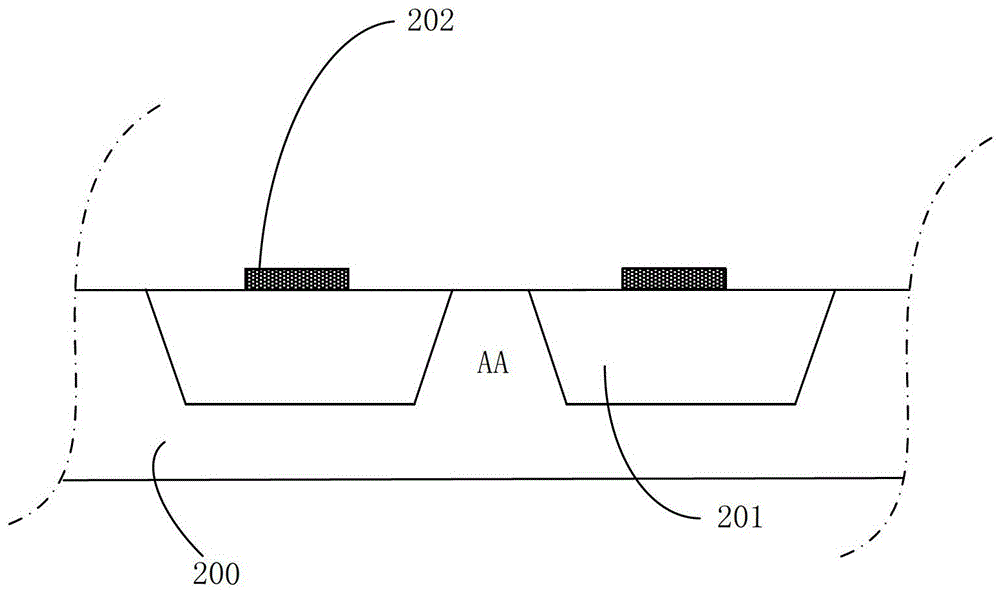
The invention provides a manufacturing method of a semiconductor device, and relates to the semiconductor technical field; the method comprises the following steps: S101, providing a semiconductor substrate; S102, forming an antireflective layer in a boundary between a zone wherein ion injection is to be carried out and a zone wherein an ion implantation shielding layer is to be formed on the semiconductor substrate; S103, employing photoresist to form the ion implantation shielding layer on the semiconductor substrate. The manufacturing method of the semiconductor device adds the step in which the antireflective layer is formed in a boundary between the zone wherein ion injection is to be carried out and the zone wherein the ion implantation shielding layer is to be formed; in a process to expose a photoresist film so as to form the ion implantation shielding layer, the reflection light from the semiconductor substrate can be prevented or stopped from entering the photoresist film, so the reflection light cannot cause size reduction of the ion implantation shielding layer, thereby ensuring key size of the ion implantation shielding layer, and improving performance of the semiconductor device.

Description

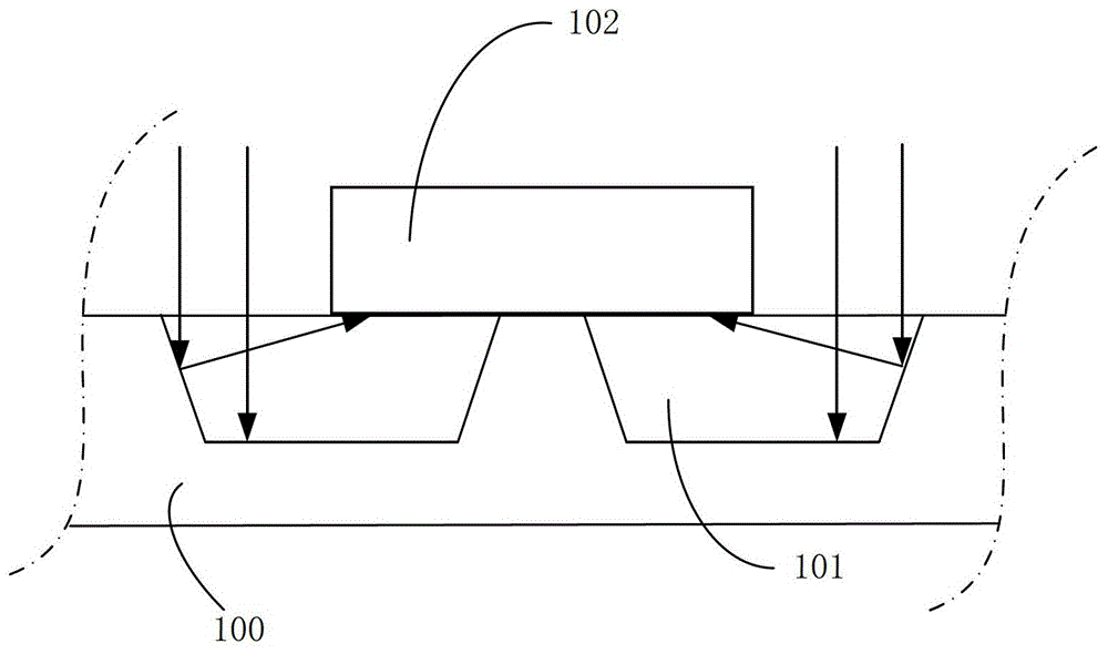
technical field [0001] The invention relates to the technical field of semiconductors, in particular to a method for manufacturing a semiconductor device. Background technique [0002] In the field of semiconductor technology, with the rapid development of nano-processing technology, the feature size of transistors has entered the nanoscale. With the continuous reduction of device size, the critical dimension (CD) and alignment accuracy (overlay tolerance) of the ion implantation masking layer (IMP block layer) are also rapidly shrinking to meet the ever-reducing device size. need. [0003] Correspondingly, the reflectivity and shape changes of the semiconductor substrate under the ion-implantation masking layer (generally photoresist) have brought more and more serious influence on the critical dimensions of the ion-implantation masking layer. like figure 1 As shown, in the existing semiconductor device manufacturing process, due to the topographical characteristics of t...

Claims


Application Information

Patent Timeline
Patent Type & Authority Patents(China)
IPC IPC(8): H01L21/02
CPCH01L21/027H01L21/0276
Inventor 舒强胡华勇
Owner SEMICON MFG INT (SHANGHAI) CORP
Learn More