Vertical air conditioner indoor unit

A vertical air conditioner and indoor unit technology, applied in air conditioning system, heating method, space heating and ventilation, etc., can solve the problem of high price of air conditioner, and achieve the effect of keeping the shell compact

Inactive Publication Date: 2016-09-07
DAIKIN IND LTD
View PDF7 Cites 0 Cited by
  • Summary
  • Abstract
  • Description
  • Claims
  • Application Information

AI Technical Summary

Problems solved by technology

[0008] However, if the air conditioner of Patent Document 1 is to be configured so that air can be blown from the upper exhaust port and the lower exhaust port using two heat exchangers, the air conditioner will become an expensive device.

Method used


Image

  • Vertical air conditioner indoor unit
  • Vertical air conditioner indoor unit
  • Vertical air conditioner indoor unit

Examples


no. 1 Embodiment approach

[0051] (1) Refrigerant circuit of air conditioner

[0052] figure 1 It is a circuit diagram showing the outline of the structure of an air conditioner having a vertical air conditioner indoor unit. Such as figure 1 As shown, the air conditioner 10 according to the first embodiment includes a vertical air conditioner indoor unit 20 that is placed on the floor or the like indoors. The air conditioner 10 mainly includes an outdoor unit 30 installed outdoors in addition to the vertical air conditioner indoor unit 20 . exist figure 1 In , the solid line connecting each device indicates refrigerant piping, and the dotted line connecting each device indicates a signal transmission line.

[0053] The outdoor unit 30 is connected to the vertical air conditioner indoor unit 20 installed indoors through a refrigerant pipe, and constitutes a refrigerant circuit of the air conditioner 10 together with the vertical air conditioner indoor unit 20 . Therefore, the vertical air conditione...

no. 2 Embodiment approach

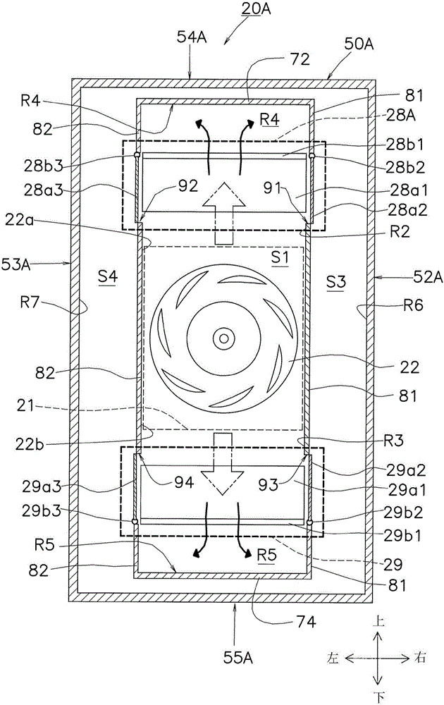
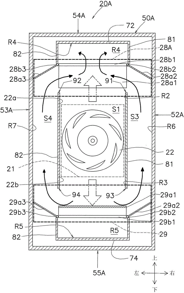
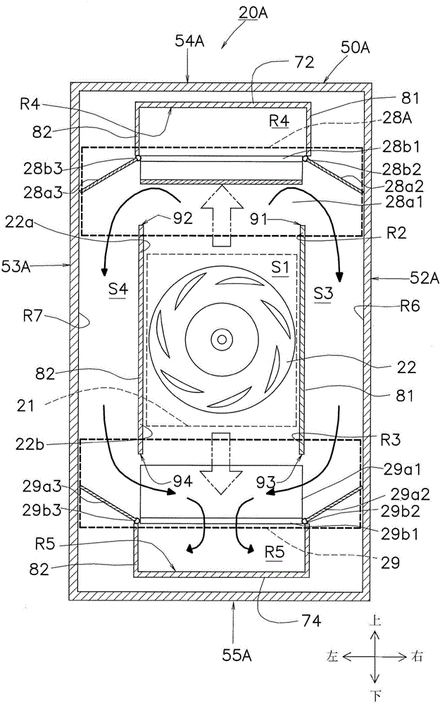
[0113](8) Outline of the structure of the vertical air conditioner indoor unit

[0114] Below, use Figure 7 ~ Figure 12 The vertical air conditioner indoor unit according to the second embodiment will be described. The vertical air conditioner indoor unit 20A according to the second embodiment also has the indoor heat exchanger 21 and the indoor fan 22 similarly to the vertical air conditioner indoor unit 20 of the first embodiment. The indoor unit 20A is installed in place of the vertical air conditioner indoor unit 20 of the first embodiment. figure 1 In the circuit shown, it is suitable for the air conditioner 10.

[0115] In addition, the vertical air conditioner indoor unit 20A also has an indoor control device 49a, a liquid-side temperature sensor 24, a gas-side temperature sensor 25, and a room temperature sensor 26. Based on the measurement results of these temperature sensors 24-26, the indoor control device 49a (control device) 49) Control the vertical air condit...


PUM


Abstract

PROBLEM TO BE SOLVED: To provide an inexpensive floor type air conditioner capable of blowing sufficiently conditioned air from an upper air outlet and a lower air outlet.SOLUTION: An upper passage R2 continuously extends from an upper outlet 22a of an indoor fan 22 to an upper part flow path selection mechanism 28, and a lower passage R3 continuously extends from a lower outlet 22b of the indoor fan 22 to a lower part flow path selection mechanism 29. A bypass passage R1 is connected to the upper part flow path selection mechanism 28 and the lower part flow path selection mechanism 29. The upper part flow path selection mechanism 28 is constructed to select the state that conditioned air passes through the upper passage R2 to an upper air outlet 58 or the state that the conditioned air passes from the upper passage R2 through the bypass passage R1 to a lower air outlet 59. The lower part flow path selection mechanism 29 is constructed to select the state that conditioned air passes from the lower passage R3 to the lower air outlet 59 or the state that the conditioned air passes from the lower passage R3 through the bypass passage R1 to the upper air outlet 58.

Description

technical field [0001] The present invention relates to a vertical air conditioner indoor unit, in particular to a vertical air conditioner indoor unit with exhaust ports on the upper and lower parts of the casing. Background technique [0002] Conventionally, there is known an air conditioner that has an upper exhaust port and a lower exhaust port, sucks in air from the center, tempers the sucked air with a heat exchanger, and blows the air out from the upper exhaust port and the lower exhaust port. . [0003] For example, in the conventional air conditioner shown in Patent Document 1 (Japanese Unexamined Patent Application Publication No. 2009-257709), only sufficiently conditioned air can be blown out from either the upper exhaust port or the lower exhaust port using a single heat exchanger. Air. [0004] Therefore, Patent Document 1 proposes an air conditioner in which sufficiently conditioned air is blown out from both the upper exhaust port and the lower exhaust port...

Claims


Application Information

Patent Timeline
Patent Type & Authority Patents(China)
IPC IPC(8): F24F1/00F24F13/08F24F13/30
Inventor 伊东干夫仲田贵裕尾古孝彦
Owner DAIKIN IND LTD
Why Eureka
Try Eureka