Piston ring
A piston ring and plate-shaped technology, applied to the field of piston rings for internal combustion engines, can solve the problems of insufficient durability, inability to maintain the prevention of aluminum adhesion for a long time, and difficulty in maintaining the film for a long time, and achieve an excellent effect of preventing aluminum adhesion
- Summary
- Abstract
- Description
- Claims
- Application Information
AI Technical Summary
Problems solved by technology
Method used
Image
Examples
Embodiment 1)
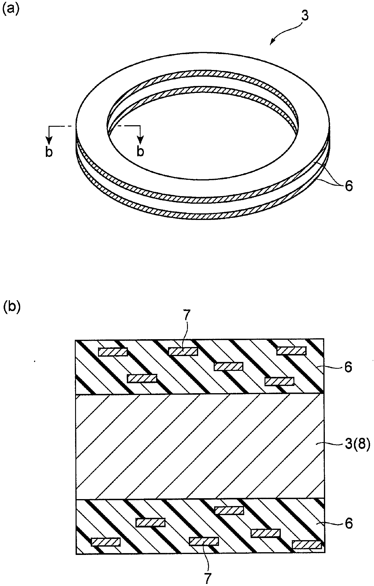
[0044] A CrN film with a thickness of about 30 μm is formed on the outer peripheral surface of a piston ring made of low-chromium steel by ion spraying. After alkali degreasing the obtained piston ring, it was immersed in a manganese phosphate aqueous solution heated to about 80° C. for 5 minutes to form a manganese phosphate film with a thickness of about 2 μm on the surface other than the outer peripheral surface of the piston ring. Add plate-shaped alumina powder (plate-shaped filler) with an average particle size of 10 μm and an aspect ratio of 100 to polyimide varnish (RC5057 manufactured by I.S.T Co., Ltd.) as a filler (additive material), and fully carry out using a mixer After stirring, the coating solution for coating was prepared by using a three-roll mill with the minimum roll interval. Here, the amount of the plate-like alumina powder added was adjusted to be 10% by volume based on the entire film. The upper and lower surfaces of the piston ring on which the manga...
Embodiment 2)
[0046] Tabular alumina powder with an average particle size of 10 μm and an aspect ratio of 100 is added to a liquid obtained by diluting polyamide-imide resin (Toyobo Co., Ltd. HR13NX) with N-methyl-2-pyrrolidone (Plate-like filling material) was thoroughly stirred with a mixer, and then prepared into a coating solution for coatings by passing through a Sanbon roller mill with the minimum roll interval. Here, the amount of the plate-like alumina powder added was adjusted to be 10% by volume based on the entire film. Using the obtained coating solution, a resin-based film was formed on the upper surface and the lower surface of the same piston ring as in Example 1 by the same method as in Example 1. The thicknesses of the coatings on the upper surface and the lower surface of the piston ring were both about 10 μm.
Embodiment 3)
[0048] Except that the plate-shaped filler material was changed from alumina powder to plate-shaped silicon carbide powder (average particle size: 10 μm, aspect ratio: 100), under the same conditions as in Example 1, on the upper surface and lower surface of the piston ring, A resin film is formed on the surface. The thicknesses of the coatings on the upper surface and the lower surface of the piston ring were both about 10 μm.
PUM
 Abstract
Description
Claims
Application Information
 - Generate Ideas
- Intellectual Property
- Life Sciences
- Materials
- Tech Scout
- Unparalleled Data Quality
- Higher Quality Content
- 60% Fewer Hallucinations
Browse by: Latest US Patents, China's latest patents, Technical Efficacy Thesaurus, Application Domain, Technology Topic, Popular Technical Reports.
© 2025 PatSnap. All rights reserved.Legal|Privacy policy|Modern Slavery Act Transparency Statement|Sitemap|About US| Contact US: help@patsnap.com


