
Laser scattering displayer

A laser scattering and display technology, which is applied in the direction of instruments, TVs, color TV parts, etc.

Inactive Publication Date: 2014-05-07
严守权
View PDF8 Cites 5 Cited by
  • Summary
  • Abstract
  • Description
  • Claims
  • Application Information

AI Technical Summary

Problems solved by technology

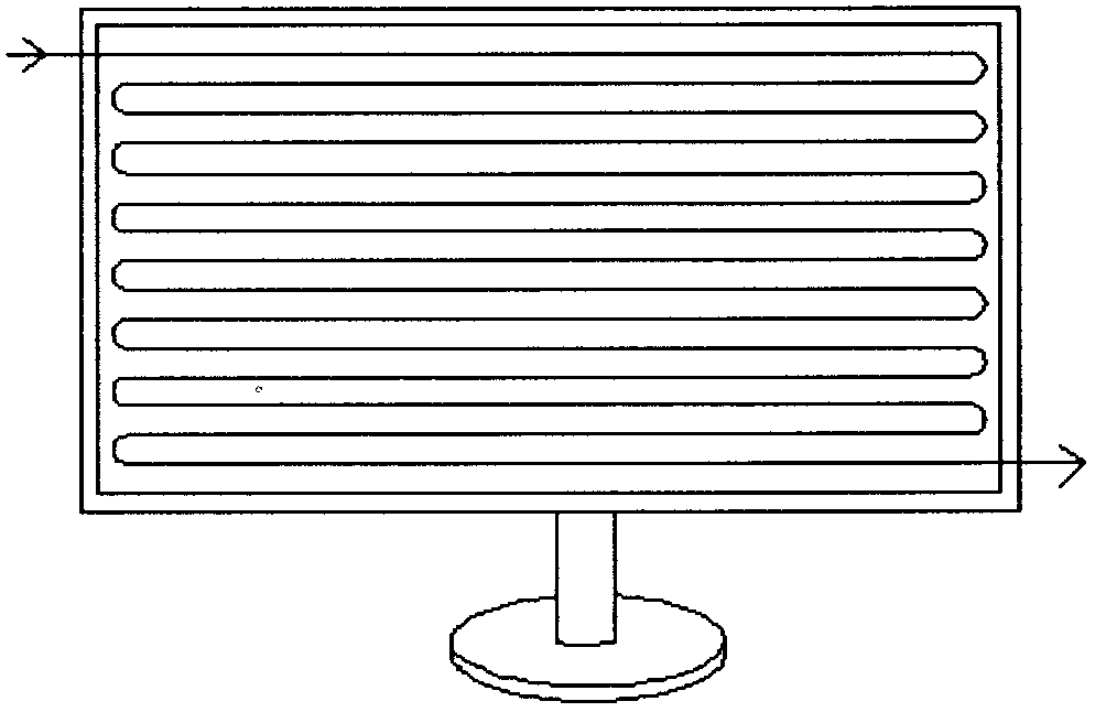
[0005] The purpose of the present invention is to solve the problem of laser scanning, how to obtain fast, stable, long-life, small and structurally diverse displays in an efficient and simple way

Method used


Image

  • Laser scattering displayer
  • Laser scattering displayer
  • Laser scattering displayer

Examples


Embodiment Construction

[0010] The laser scattering display mainly uses liquid crystal material as the light transmission medium, and the method is as follows:

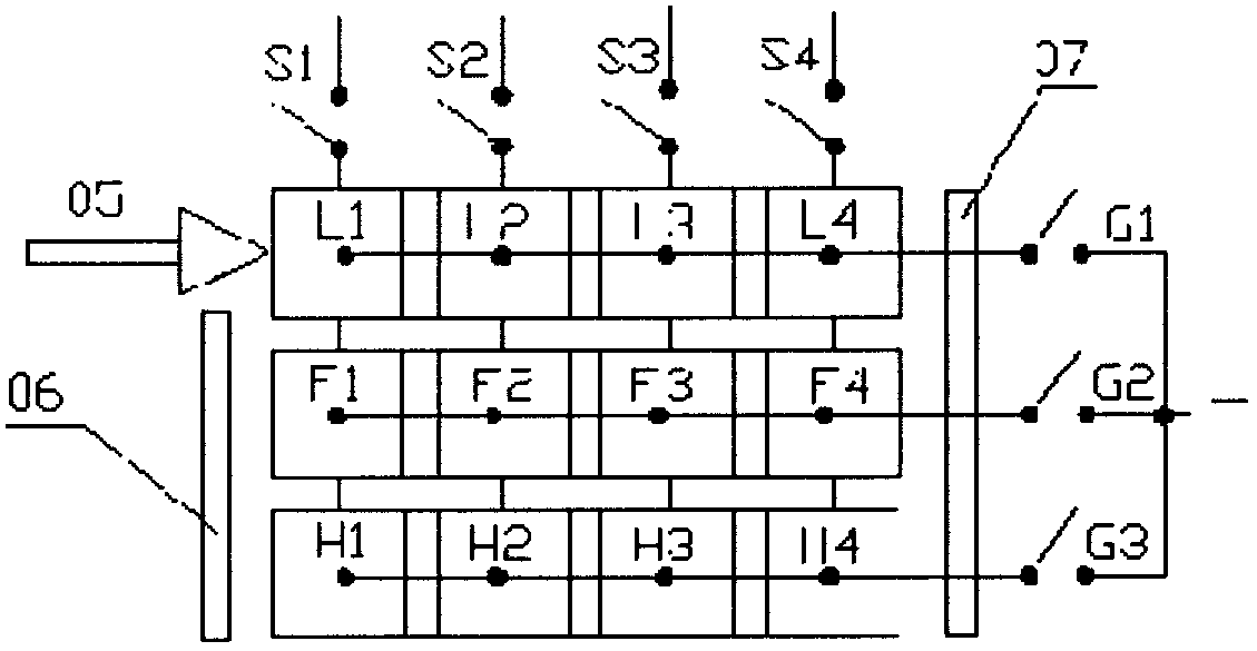
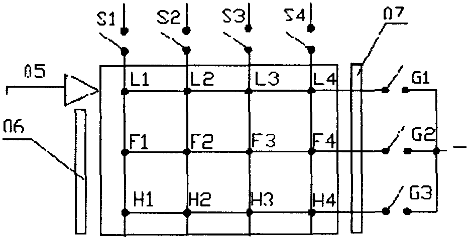
[0011] Method 1: First, engrave a series of grooves on the surface of the display panel to place the wires. The positions of the grooves are consistent with the pixels, and then print a transparent conductor material. Clean up the excess conductors on the plane, leaving only the grooves The conductor in the trench becomes a row wire after the conductor in the trench is solidified. One end of the row wire ends at the last pixel position, and the other end is connected to the row driver IC. Use the same method to make another panel with column wires, the difference is that the grooves are arranged in columns to connect the column driver ICs. Make a screen with transparent insulating material, the number, size, and position of the grid are consistent with the pixels, and the refractive index of the screen is consistent with that of the liquid c...


PUM


Abstract

The invention discloses a laser scattering displayer. On the basis of the principle of the laser scattering displayer, lasers are used as a light source, the lasers are transmitted to pixel positions of a display screen through optical fibers, light transmission media made of special materials are arranged at the pixel positions, the media can generate physical or chemical changes under the action of currents or a magnetic field, the lasers are made to generate scattered light or transparent non-scattered light, and when the scattered light is distributed at each pixel position, the scattered light is used as pixels; when the scattered light does not exist, the pixel positions are transparent and used as laser paths, the existence of the scattered light determines whether the pixels are turned on or off, a plurality of the pixels form images, and image restoration is achieved. The laser scattering displayer is simple in production process, low in cost and suitable for television screens, computer screens, phone screens, electromechanical instruments and the like. The designed product is stable and reliable in performance and durable in use. The laser scattering displayer is more suitable for 3D televisions, three-dimensional televisions in the future and the like.

Description

technical field [0001] The present invention designs a laser scattering display, which uses three primary color lasers to mix as a light source, and transmits the laser light to the pixel position on the display screen through a light transmission medium, and the light transmission medium at the pixel position undergoes physical or chemical changes under the action of an electric current, so that the laser light spreads The path changes and spreads out of the display screen, and the point-changed light is used as pixels to form a picture. The design of the present invention is applicable to TV screens, computer screens, mobile phone screens, electromechanical instruments and the like. It is also suitable for 3D TV and future three-dimensional stereo TV. Background technique [0002] CRT TVs have good color, but they emit radiation and are too bulky to meet the needs of large screens. LCD TVs need backlights to illuminate and use liquid crystals to control pixels. The contr...

Claims


Application Information

Patent Timeline
Patent Type & Authority Applications(China)
IPC IPC(8): G09F9/35H04N5/44
Inventor 严守权
Owner 严守权
Learn More