
Electronic device interconnection body

A technology for electronic devices and interconnects, applied in the field of integrated circuit semiconductor packaging, can solve the problems of time-consuming, time-consuming and difficult manufacturing processes

Inactive Publication Date: 2014-04-30
申宇慈
View PDF8 Cites 2 Cited by
  • Summary
  • Abstract
  • Description
  • Claims
  • Application Information

AI Technical Summary

Problems solved by technology

It should be pointed out that it is difficult to achieve a height of 300 microns for interconnect bumps based on the process steps of opening holes and then filling them
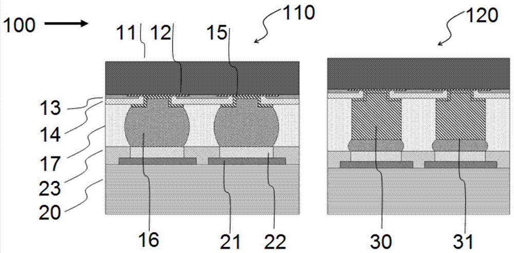
[0009] The prior art methods used to manufacture flip-chip packages or interconnects have a number of limitations, including: 1) The via-then-fill process step produces interconnect bumps typically below about 100 microns in height, And its manufacturing process is very time-consuming and expensive. 2) It is more time-consuming and expensive to use a wire welder to manufacture metal wire supports one by one on the pad, and then use solder to form bumps on the metal wire support. The claimed interconnection bump height is only 300 microns. 3) It is very difficult to manufacture interconnections with a fine bump pitch (Fine Bump Pitch) and a certain height, such as a bump pitch of less than 50 microns and a height of more than 100 microns 4) The gradual improvement of these interconnection technologies has not fundamentally solved the stress caused by the mismatch of thermal expansion coefficient between the chip and the substrate and the interconnection failure or cracking caused by it
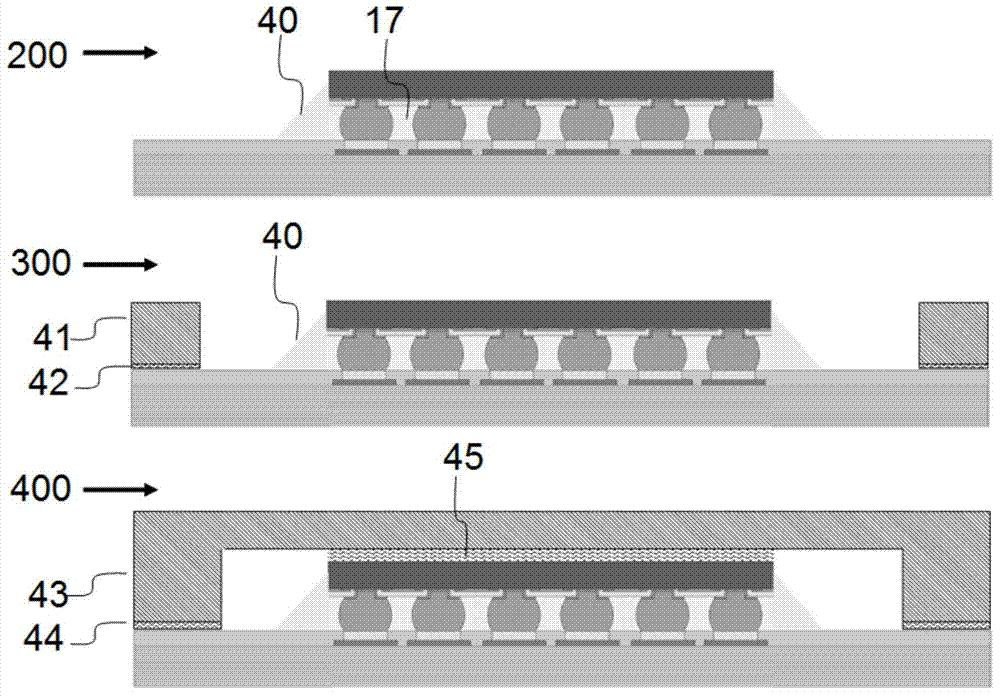
[0010] It should be pointed out that, Figure 1A and Figure 1B These components in the illustrated flip-chip package, namely the second inert protective layer 14 on the chip, the underfill material 17, the stiffener ring 41 and the cover 43 are all intended to improve the structural reliability of the package or interconnection from overshooting. Crack or fail prematurely regardless of increased functionality of the semiconductor chip; in other words, if there are no structural reliability issues with the package or interconnect, there is no need for these components, which take up most of the manufacturing flip-chip packaging time and cost

Method used


Image

  • Electronic device interconnection body
  • Electronic device interconnection body
  • Electronic device interconnection body

Examples


Embodiment Construction

[0044] In order to clearly describe specific embodiments of the present invention by referring to the accompanying drawings, some terms used are first explained as follows: 1) Unidirectional conductive plate, which represents a sheet that conducts electricity in the thickness direction of the plate and insulates in the in-plane direction of the plate Shaped material, where conduction in the thickness direction of the plate does not mean that any position of the plate is conductive in the thickness direction of the plate, but means that on a relatively large scale, any position of the plate conducts electricity in the thickness direction of the plate, or means Conduct electricity in the thickness direction of the board at the positions arranged at a set interval; while for the substrate bonding material is a conductive material, such as a low-melting point metal material, unidirectional conduction means that the conductors are insulated from each other in the in-plane direction o...


PUM


Abstract

The invention discloses an electronic device interconnection body on the basis of a one-way conductive board. The electronic device interconnection body is characterized in that the surface of the one-way conductive board comprises exposed wires used for being connected with an electronic device, the arrangement and the intervals of the exposed wires are set, the heights of the exposed wires can be different, so that step-shaped grooves are formed, the length of each wire can range from about 100 microns to about 200 microns, the aspect ratio of each wire can range from about 2 to about 2000, and each exposed wire can be composed of a wire body or a wire bundle composed of multiple wire bodies or a wire rope composed of multiple wire bodies. The electronic device interconnection body is formed by the electronic device and the one-way conductive board and preferably, the electronic device interconnection body also can be formed by multiple semiconductor chips and a circuit board through the one-way conductive board. The stacking or inner-face interconnection mode of the semiconductor chips is adopted by the electronic device interconnection body.

Description

technical field [0001] The present invention generally relates to integrated circuit semiconductor package technology, in particular to the conductive interconnection technology between integrated circuit semiconductor chip and its package and circuit substrate or printed circuit board. Background technique [0002] Since the flip chip interconnection technology can accommodate a very high number of input and output ports or pins per unit area, it is widely used in the packaging of semiconductor devices, where the outer end of the input and output ports arranged on the surface of the flip chip is usually a The pads are interconnected with corresponding pads on the circuit substrate or printed circuit board through metal bumps, so as to achieve mutual communication between the flip chip and the circuit substrate or printed circuit board. In the flip-chip interconnection technology, since the chip faces down and is interconnected with the circuit substrate or printed circuit b...

Claims


Application Information

Patent Timeline
Patent Type & Authority Applications(China)
IPC IPC(8): H01L23/535
CPCH01L23/49827H01L23/13H01L23/49811H01L2224/16225H01L2224/32225H01L2224/73204H01L2224/73253H01L2924/00
Inventor 申宇慈
Owner 申宇慈
Learn More