A near-infrared laser spot field of view parameter measurement device and measurement method
A laser parameter and laser spot technology, which is applied in the direction of measuring devices, optical devices, instruments, etc., can solve the problems of failure to realize automatic measurement, large measurement error, and no automatic test infrared laser spot.
- Summary
- Abstract
- Description
- Claims
- Application Information
AI Technical Summary
Problems solved by technology
Method used
Image
Examples
Embodiment 1
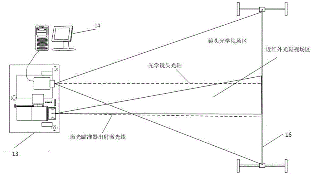
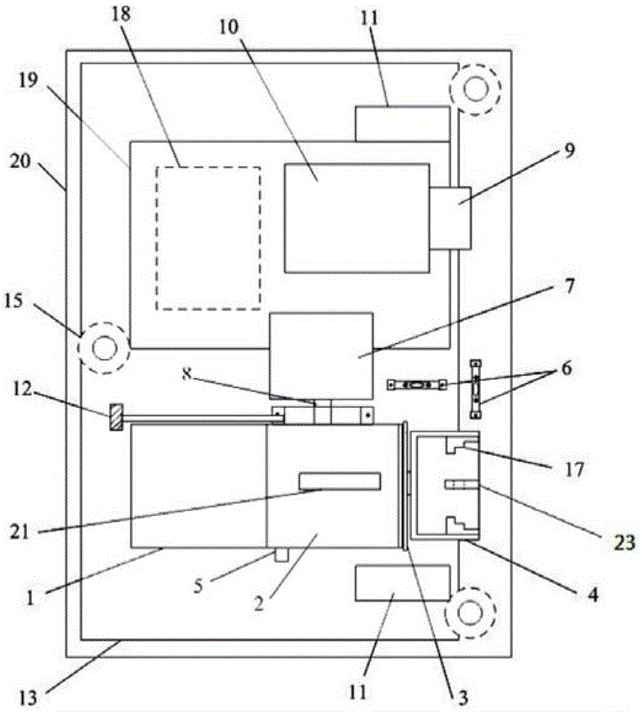
[0040] Such as Figure 1-4 As shown, a near-infrared laser spot field parameter measurement device is shown, which includes a near-infrared laser parameter test bench 13, a computer 14, and a calibration grid board 16, wherein the computer 14 is equipped with processing and calculation software, the near-infrared laser The parameter test bench 13 includes a transmitting device capable of emitting near-infrared laser. The measuring device also includes a chassis base 20, the near-infrared laser parameter test bench 13 can be fixed on the chassis base 20, and the chassis base 20 is placed horizontally through at least three leveling bases 15 installed at its edges. On the ground or on the platform, each leveling base 15 can be used to adjust the height of the chassis base 20 to ensure that the entire near-infrared laser parameter test bench 13 is in a horizontal state. There are also two levels on the chassis base 20 Observe the water bubble to observe the horizontal state of th...
Embodiment 2
[0063] According to the operation steps of embodiment 1, if the pitch direction adjustment mechanism 2 and the concentric axis rotation adjustment mechanism 4 in the measurement specific step 5 are adjusted, the spot of the calibration laser 23 is located on the calibration grid plate 16, and the pitch direction rotation adjustment is recorded The visible laser sight 21 above the mechanism 2 is calibrating the new coordinate point of the grid plate see Figure 5 , Then ∠OFO 2 It is the angle β between the centerline of the near-infrared laser emission spot and the centerline of the main axis of the laser product. According to the coordinates O(x,y), O 0 (x 0 ,y 0 ) Get OO 2 And OO 0 Distance, press ΔOFO 2 , ΔO 2 O 0 F and ΔOO 0 F, combined with the pitch angle θ read by the thirteen-bit angle encoder 7, β can be calculated.
[0064] β = arccos OF 2 + O 2 F 2 - O 2 O 2 2 · OF · O 2 F
[0065] among them, O 2 F=L 0...
PUM
 Abstract
Description
Claims
Application Information
 - R&D
- Intellectual Property
- Life Sciences
- Materials
- Tech Scout
- Unparalleled Data Quality
- Higher Quality Content
- 60% Fewer Hallucinations
Browse by: Latest US Patents, China's latest patents, Technical Efficacy Thesaurus, Application Domain, Technology Topic, Popular Technical Reports.
© 2025 PatSnap. All rights reserved.Legal|Privacy policy|Modern Slavery Act Transparency Statement|Sitemap|About US| Contact US: help@patsnap.com


