
Coating machine crucible device

A coating machine and crucible technology, applied in the field of coating machine crucible equipment, can solve problems such as large temperature difference and unstable evaporation rate

Active Publication Date: 2014-04-30
TCL CHINA STAR OPTOELECTRONICS TECH CO LTD
View PDF4 Cites 18 Cited by
  • Summary
  • Abstract
  • Description
  • Claims
  • Application Information

AI Technical Summary

Problems solved by technology

The difference between the evaporation temperature of the organic material and its cracking temperature is very small, and the temperature difference inside the crucible is often large, which may easily cause the evaporation rate to be unstable

Method used


Image

  • Coating machine crucible device
  • Coating machine crucible device
  • Coating machine crucible device

Examples


Embodiment Construction

[0018] The specific embodiments of the present invention will be further described below in conjunction with the accompanying drawings.

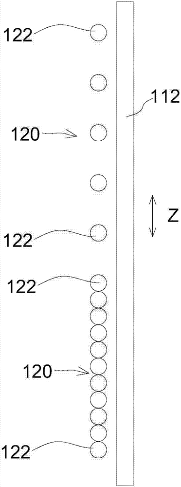
[0019] like figure 1 As shown, the coating machine crucible device 100 of this embodiment includes a barrel structure 112 , a plurality of heaters 120 , a crucible 110 , a plurality of temperature sensors 160 and a plurality of driving mechanisms 200 . Wherein, the plurality of heaters 120 are distributed in the barrel structure 112 along the longitudinal direction Z and are used to heat the materials contained in the crucible 110 . The plurality of temperature sensors 160 are distributed in the crucible 110 along the longitudinal direction Z to measure the temperature of different longitudinal regions of the crucible 110 . The multiple driving mechanisms 200 are used to move at least one heater 120 among the multiple heaters 120 along the longitudinal direction Z to control the temperature distribution in the crucible 110 . In this way, t...


PUM


Abstract

The invention discloses a coating machine crucible device. The coating machine crucible device (100) comprises a bucket-shaped structure (112), a plurality of heaters (120), a crucible (110), a plurality of temperature sensors (160) and a plurality of driving mechanisms (200), wherein the heaters (120) are longitudinally distributed in the bucket-shaped structure (112) and are used for heating materials in the crucible (110), the temperature sensors (160) are longitudinally distributed in the crucible (110) and are used for measuring the temperature in the crucible (110), and the driving mechanisms (200) are used for driving at least one heater (120) in multiple heaters (120) to longitudinally move so as to control the temperature distribution in the crucible (110). According to the coating machine crucible device, by changing the longitudinal distribution density of the heaters, the longitudinal temperature distribution of the crucible can be controlled, and then the evaporation velocity is controlled and stabilized.

Description

technical field [0001] The invention relates to a coating machine crucible device. Background technique [0002] The thermal evaporation method is mainly to heat the organic material contained in the crucible equipment of the coating machine in a vacuum environment, so that the sublimated or molten organic material is vaporized at a high temperature, and deposited on the TFT structure or the anode structure of the thin film field effect transistor. on the substrate. The difference between the evaporation temperature of the organic material and its pyrolysis temperature is very small, and the temperature difference inside the crucible is often large, which may easily cause the evaporation rate to be unstable. Contents of the invention [0003] The purpose of the present invention is to provide a coating machine crucible device, which can control the evaporation rate to make it stable. [0004] The present invention is realized through the following technical solutions: a ...

Claims


Application Information

Patent Timeline
Patent Type & Authority Applications(China)
IPC IPC(8): C23C14/26C23C14/54
CPCC23C14/243C23C14/26C23C14/543
Inventor 张鑫狄李冠政
Owner TCL CHINA STAR OPTOELECTRONICS TECH CO LTD
Learn More