
Fiber separation screen

A technology of fiber separation and screen mesh, applied in the direction of filtration separation, separation method, mobile filter element filter, etc., can solve the problems of high equipment power, poor material separation effect, and many materials, so as to achieve high production capacity and improve stability. the effect of reducing product cost

Active Publication Date: 2014-04-30
烟台鼎丰生物科技有限公司
View PDF5 Cites 4 Cited by
  • Summary
  • Abstract
  • Description
  • Claims
  • Application Information

AI Technical Summary

Problems solved by technology

[0003] (1) The translational rotary vibrating screen is difficult to separate materials higher than 5°Be;
[0004] (2) Pressure curved sieve, pressure curved sieve is a static high-efficiency screening equipment, which separates and classifies wet materials by pressure, and the slurry flows from the nozzle at a certain speed (15-25m / s) The tangential direction of the sieve surface enters the concave sieve surface, and the high feed speed causes the material to be subjected to centrifugal force, gravity and the resistance of the sieve bars on the sieve surface, and the material flows from one sieve bar to another. During the process, the sharp edge of the sieve bar cuts the material. At this time, the starch and a large amount of water in the material pass through the sieve gap to become the undersize material, while the fine fiber residue flows out from the end of the sieve surface to become the oversize material. , but the material separation effect is poor, and it is not easy to separate the finer fibers above 180 mesh;
The screen basket is fixed by a cantilever, the small end is fixed, and the large end is suspended. The accumulation of materials at the large end will increase the bending moment and stress of the screen basket, thus increasing the requirements for the strength and stiffness of the screen basket. This is in the design is a disadvantage
[0006] The three kinds of separation screens mentioned above require material concentration below 5°Be, large water consumption, separation mesh below 120 mesh, high equipment power, large amount of materials, and large energy consumption.

Method used


Image

  • Fiber separation screen
  • Fiber separation screen
  • Fiber separation screen

Examples


Embodiment Construction

[0027] The principles and features of the present invention are described below in conjunction with the accompanying drawings, and the examples given are only used to explain the present invention, and are not intended to limit the scope of the present invention.

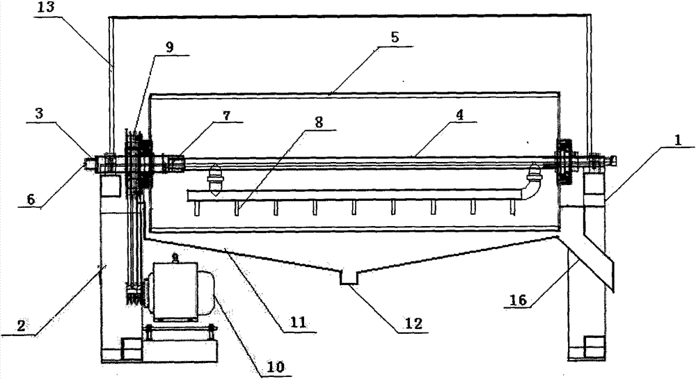
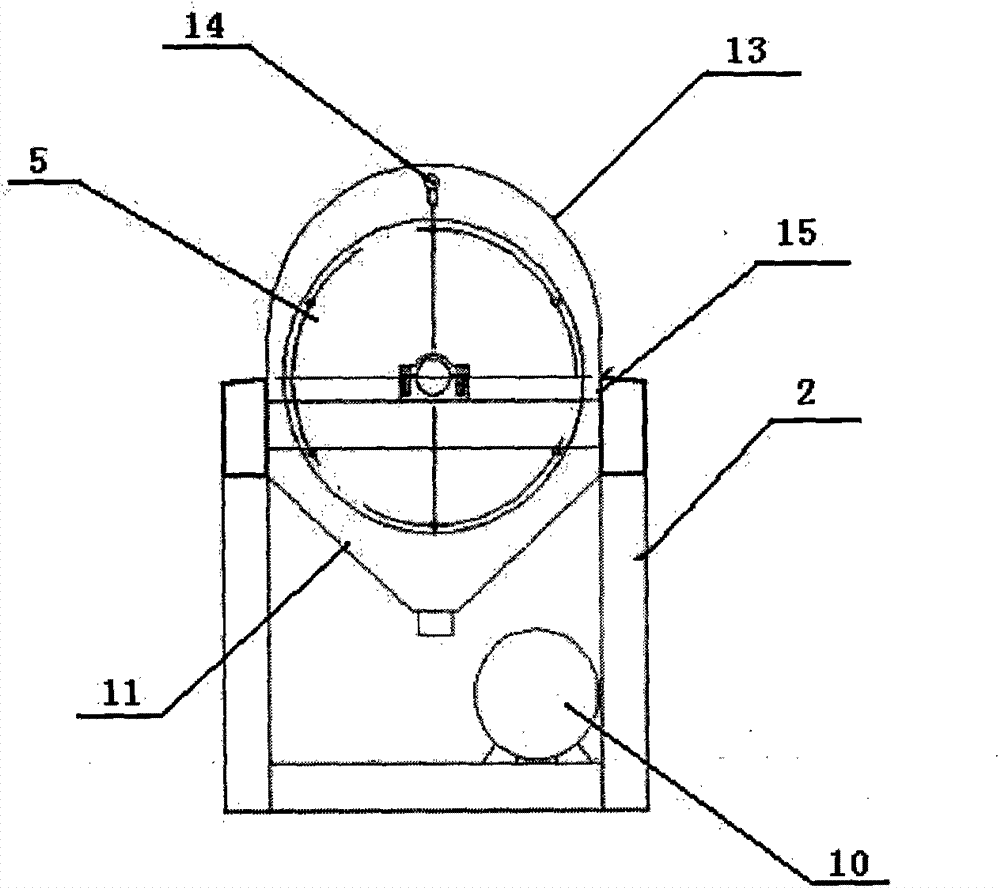
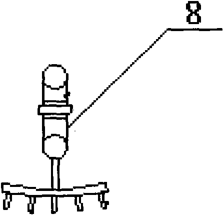
[0028] A fiber separation screen, comprising a screen body 1, which is special in that the screen body 1 includes a support device 2, and the upper end of the support device 2 is provided with a feed pipe 3 fixedly connected by a shaft, a water inlet pipe 4 and a Drum screen 5, the feed pipe 3 is provided with a feed port 6 and a discharge port 7, the lower end of the water inlet pipe 4 is provided with several high-pressure nozzles 8, the discharge port 7 and the high-pressure nozzle 8 passes into the inside of the drum screen 5; the drum screen 5 is connected with a transmission device 9, and the transmission device 9 is connected with the power unit 10; Device 11, the bottom of the starch water collecting device ...


PUM


Abstract

The invention belongs to the technical field of starch separation treatment, and in particular relates to a fiber separation screen, which comprises a screen body, wherein the screen body comprises a support device, wherein a feed pipe, a water inlet pipe and drum type screen cloth are arranged at the upper end of the support device, and are fixedly connected with one another through a shaft; the feed pipe is provided with a feed hole and a discharge hole; a plurality of high-pressure sprinklers are arranged at the lower end of the water inlet pipe; the discharge hole and the high-pressure sprinklers lead into the drum type screen cloth; a transmission device is connected to the drum type screen cloth, and is connected with a power device; a starch water collection device is arranged below the drum type screen cloth; a starch water discharge hole is formed in the lower part of the starch water collection device; a soybean residue collection device is connected to the lateral surface of the starch water collection device. The fiber separation screen has high production capacity and good separation effects, is energy-conserving and environmentally friendly, and is the most reasonable screening equipment for fiber separation in the starch industry at present, the running stability of the fiber separation screen is greatly improved, the cost of the product is lowered, and water and electricity are saved.

Description

technical field [0001] The invention belongs to the technical field of starch separation and treatment, and in particular relates to a fiber separation sieve. Background technique [0002] At present, the starch industry generally uses the following three types of separation sieves: [0003] (1) The translational rotary vibrating screen is difficult to separate materials higher than 5°Be; [0004] (2) Pressure curved sieve, pressure curved sieve is a static high-efficiency screening equipment, which separates and classifies wet materials by pressure, and the slurry flows from the nozzle at a certain speed (15-25m / s) The tangential direction of the sieve surface enters the concave sieve surface, and the high feed speed causes the material to be subjected to centrifugal force, gravity and the resistance of the sieve bars on the sieve surface, and the material flows from one sieve bar to another. During the process, the sharp edge of the sieve bar cuts the material. At this t...

Claims


Application Information

Patent Timeline
Patent Type & Authority Applications(China)
IPC IPC(8): B01D33/11B01D33/50C08B30/00
Inventor 王克忠
Owner 烟台鼎丰生物科技有限公司
Learn More