
Liquid separation header

A header and liquid separation technology, applied in separation methods, dispersed particle separation, lighting and heating equipment, etc., can solve the problems of reduced gas-liquid separation efficiency, inconsistent fluctuation range, inconsistent liquid flow rate, etc., to reduce liquid volume, The effect of increasing the manufacturing cost and suppressing the disturbance

Active Publication Date: 2014-04-23
GUANGDONG UNIV OF TECH
View PDF8 Cites 2 Cited by
  • Summary
  • Abstract
  • Description
  • Claims
  • Application Information

AI Technical Summary

Problems solved by technology

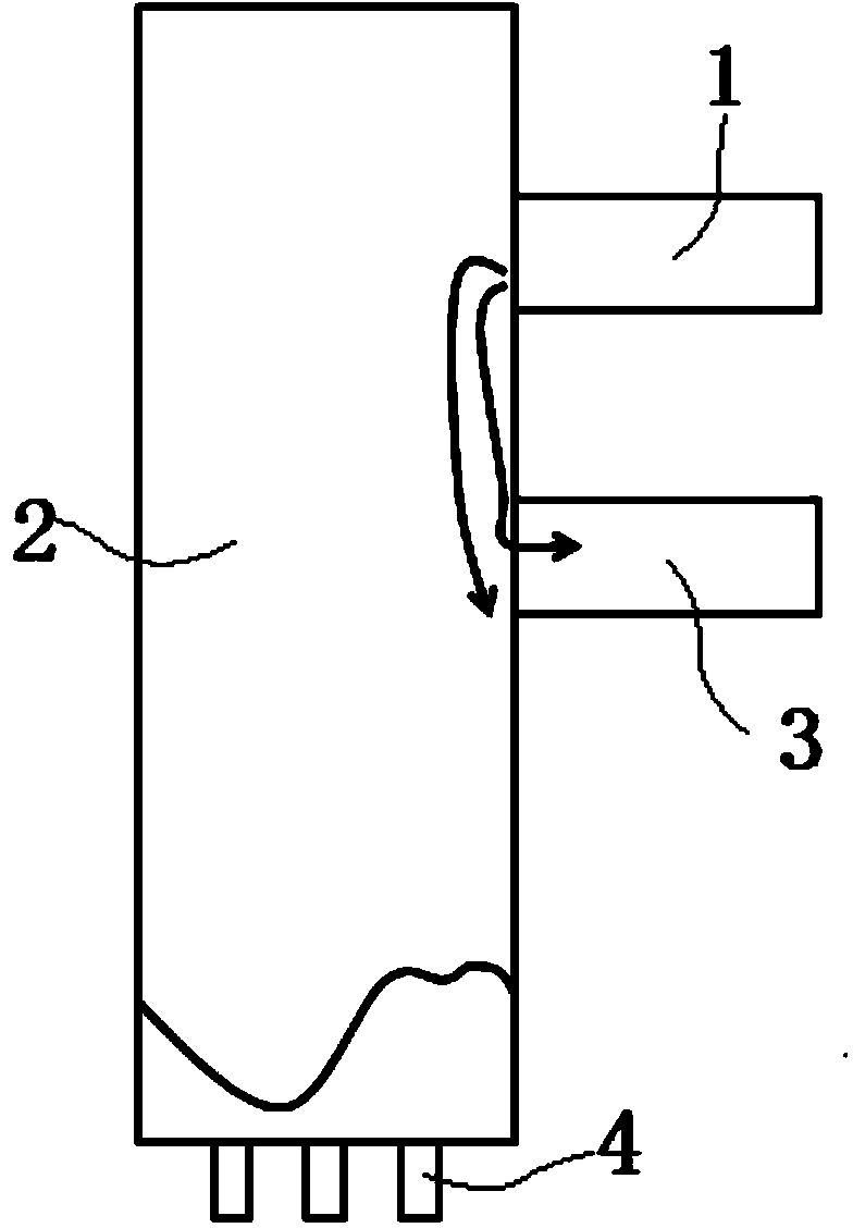
However, through the experimental research process, it is found that under certain incoming flow conditions, such as when the velocity of the incoming liquid phase is small, due to the wall adhesion, the liquid forms a wall-attached flow, so that the liquid phase can easily enter the outlet branch pipe, making the The amount of liquid flowing out of the bottom of the header decreases, and the efficiency of gas-liquid separation decreases; in addition, when the incoming flow velocity is high, it hits the inner wall of the header in the form of a jet, and since the inner wall of the header is a smooth wall, the liquid flow that shoots to the wall will be attached to the wall. The circumferential expansion flow of the wall, coupled with the influence of Coriolis acceleration and the disturbance of the airflow inside the header, the continuous liquid film is easily broken, and the large droplets are easily entrained by the airflow to form small droplets. These tiny liquid clusters are carried by the airflow Into the outflow branch pipe, which also reduces the amount of liquid entering the bottom of the header and reduces the efficiency of gas-liquid separation
In addition, the conventional orifice type liquid drainage core has an orifice structure, that is, the through holes on it are evenly distributed thin plates.
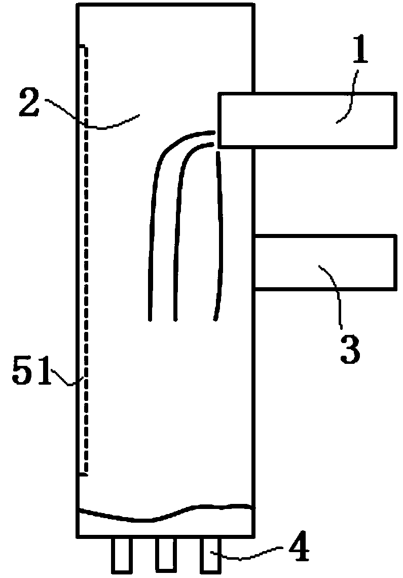
Through research, it is found that after the gas-liquid two-phase mixture entering the header along the inflow branch pipe enters the header, the impact of the airflow will also increase the disturbance of the liquid film on the upper part of the liquid discharge core, causing the upper surface of the liquid film to fluctuate, and the fluctuation amplitude is inconsistent, which in turn makes the The flow rate of the liquid passing through different areas of the liquid discharge core is inconsistent, which in turn affects the fluctuation behavior of the liquid film surface, making the flow field inside the header more complicated, and finally causing the liquid at the "peak" of the liquid film fluctuation to be carried by the airflow Go, enter the outflow branch pipe, reduce the liquid separation efficiency

Method used


Image

  • Liquid separation header
  • Liquid separation header
  • Liquid separation header

Examples


Embodiment Construction

[0024] The present invention will be described in detail below in conjunction with the accompanying drawings and specific embodiments.

[0025] A liquid header, such as figure 2 As shown, it consists of an incoming branch pipe 1, a header 2, an outflow branch pipe 3 and a drain core 4. The inflow branch pipe 1 and the outflow branch pipe 3 are round pipes arranged horizontally, the header 2 is a round pipe arranged vertically, and the inner diameter of the header 2 is about 2 to 4 times the inner diameter of the inflow branch pipe 1, This is the best way to dispense liquid. Preferably, the inner diameter of the header 2 is 12.5-25 mm. The inflow branch pipe and the outflow branch pipe are installed on the outer wall of the header and communicate with the inner chamber of the header. The incoming branch pipe 1 is installed on the outer wall of the header 2 , and one end of the incoming branch pipe 1 is inserted into the side wall of the header 2 and protrudes a little from ...


PUM


Abstract

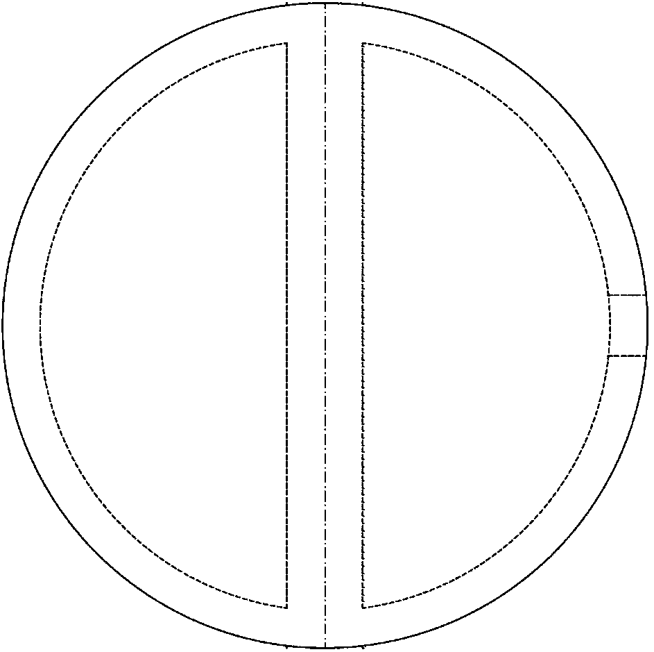
The invention discloses a liquid separation header which comprises an incoming flow branch pipe, a header, a liquid discharging core and an outflow branch pipe. The incoming flow branch pipe and the outflow branch pipe are installed on an outer side wall of the header, the liquid discharging core is installed in the header, and a liquid catching sector is arranged on an inner wall of the header. A plurality of grooves longitudinally arranged along the header and the surface with scattered protruded points or an uneven net-shaped covering layer are arranged in the liquid catching sector. The liquid separation header has the advantages that the amount of liquid flowing out along the outflow branch pipe is reduced, header inner disturbance causing reduction of liquid separation efficiency is restrained, and gas-liquid separation efficiency of the liquid separation header is improved; a process is good, almost no manufacturing cost is increased, the gas-liquid separation effect of the liquid separation header can be improved well, and the liquid separation header is high in economy and popularization value.

Description

【Technical field】 [0001] The invention relates to a liquid separation header. 【Background technique】 [0002] Publication number is that CN101025340A Chinese patent application discloses a kind of 多级冷却中间分液式空气冷凝器 , which is a heat exchanger with the characteristics of high-efficiency condensing capacity, high heat transfer coefficient, and efficient use of space. Among them, the liquid separation header is the key component, which plays the role of "gas blocking" and "liquid drainage", and finally realizes the gas Liquid separation function. The indicator to measure the performance of the liquid separation header is the liquid separation efficiency, which refers to the ratio of the amount of liquid flowing out along the bottom of the header to the total liquid amount of the incoming branch pipe. Engineering research shows that the greater the liquid separation efficiency, the higher the heat transfer efficiency of the multi-stage cooling heat exchanger. For modern society,...

Claims


Application Information

Patent Timeline
Patent Type & Authority Applications(China)
IPC IPC(8): F28F9/02B01D45/02B01D45/04
Inventor 陈颖罗向龙乐文璞郭文仙莫松平
Owner GUANGDONG UNIV OF TECH
Learn More