Bridge head structure for controlling bump at bridge head

A technology of pavement structure and abutment, which is applied in the direction of bridges, bridge parts, bridge construction, etc. It can solve the problems that the bridge structure is easily damaged, damaged, and the bonding integrity of the pavement layer and the abutment is poor, so as to achieve a good prevention of settlement Effect, overcoming weak links, and eliminating the effect of jumping phenomenon

Active Publication Date: 2014-04-23
ZHEJIANG PROVINCIAL INST OF COMM PLANNING DESIGN & RES CO LTD
View PDF5 Cites 15 Cited by
  • Summary
  • Abstract
  • Description
  • Claims
  • Application Information

AI Technical Summary

Problems solved by technology

[0007] (1) The bridge head straps are laid under the asphalt concrete surface or on the top of the flat road base, and the vehicle load is quickly transmitted to the road bed. In addition, there are two joints at the connection between the bridge abutment and the straps, such as figure 1 As shown in a and d, there is often a height difference between points a and d, and the pavement layer is easy to crack. Generally, asphalt wadding is filled in joint a as a water barrier, but in actual use, this joint is easy to be damaged by asphalt The aging of the material and the expansion and contraction of the joints make the joints empty, causing the surface water to infiltrate along the joints and directly scour the filling soil on the back of the abutment, resulting in deformation or loss of the filling soil on the back of the abutment, and finally subsidence of the subgrade soil at this place, and the subgrade below the slab Voids appear; if the subsidence of the soft ground at the bridge head is large after construction, the overall subsidence of the roadbed will also cause voids under the strapping board, and the strapping board will become a bending-tension structure, which will seriously crack or break the strapping board
[0008] (2) by figure 1 It can be seen that the two ends of a and b of the board and the fulcrum c constitute a lever. Due to the leverage effect, the settlement of the b end will produce a vertical displacement at the a end. car, which contradicts the original intention of designing the bridgehead
[0009] (3) by figure 1 It can be seen that d is the expansion joint...

Method used


Image

  • Bridge head structure for controlling bump at bridge head
  • Bridge head structure for controlling bump at bridge head

Examples


Embodiment Construction

[0038] In order to describe the present invention in more detail, the technical solution of the present invention will be described in detail below with reference to the accompanying drawings and specific embodiments.

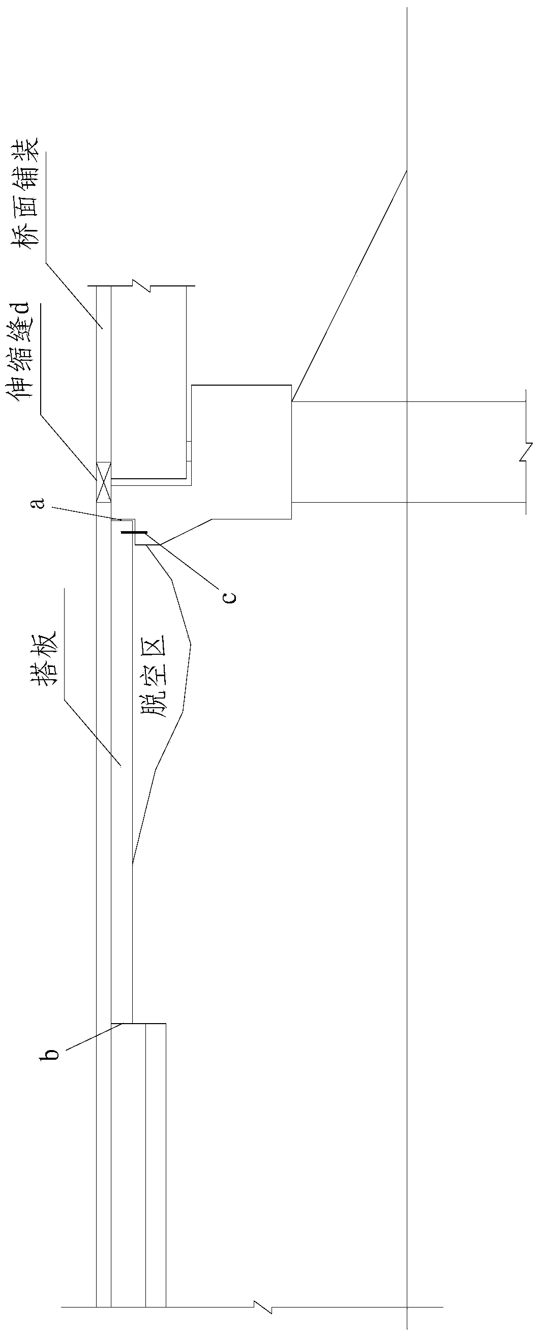
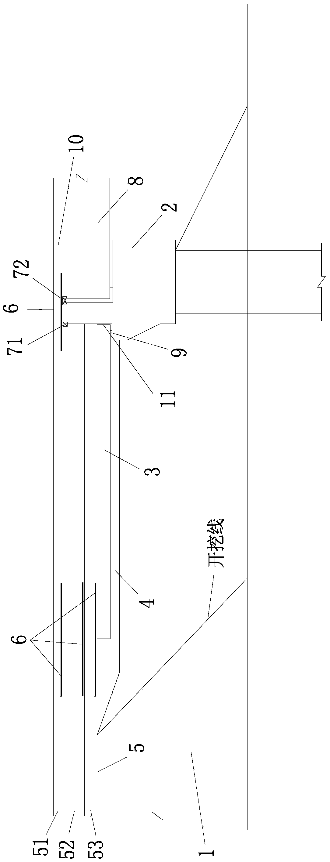
[0039] Such as figure 2 As shown, a bridge head structure used to treat bridge head bumping includes bridge abutment 2, beam slab 8, subgrade 1, pavement structure layer 5, bridge head slab 3, and bridge deck paving layer 10, and the pavement structure layer 5 is from below The upper part includes a base layer 53, a base layer 52 and a surface layer 51; the bridge head abutment 3 is set between the subgrade 1 and the base layer 53, and one end is laid on the corbel of the bridge abutment 2; a cushion layer 4 is provided under the bridge head abutment 3 There is a shrinkage joint 71 between the base layer 52 and the 2 abutment backs of the abutment, a water-stop expansion joint 72 is provided between the 2 abutment backs and the girder 8 and the surface layer 51 i...


PUM


Abstract

The invention discloses a bridge head structure for controlling bump at bridge head. The bridge head structure comprises a bridge abutment, a beam slab, a subgrade, a pavement structure layer, a bridge head transition slab and a bridge deck layer, wherein the pavement structure layer comprises a subbase layer, a base layer and a surface layer from bottom to top; the bridge head transition slab is arranged between the subgrade and the subbase layer, and one end of the bridge head transition slab is lapped on the bracket of the bridge abutment; a contraction joint is formed between the base layer and the back of the bridge abutment, and an expansion joint is formed between the back of the bridge abutment and the beam slab. The bridge head transition slab of the bridge head structure is arranged underneath so that the subgrade cavity phenomenon under the transition slab of the end near the abutment can be eliminated; as a result, differential settlement between the subgrade and the bridge can be effectively adjusted, bump at the joint of the bridge abutment and the embankment and secondary bump at the far end of the transition slab can be avoided, the reflection crack of the pavement can be prevented and controlled, the integrity of the pavement is good and the construction operation is simple and convenient; the service life of each of the pavement, the bridge head transition slab, the expansion joint and the bridge is prolonged, and therefore, an effective technical scheme for comprehensively controlling bump at bridge head is provided.

Description

Technical field [0001] The invention belongs to the technical field of bridge engineering and roadbed engineering connection, and specifically relates to a bridge head structure used for treating bridge head jumps. Background technique [0002] Bridgehead jumping is almost a common phenomenon on highway bridges in the world. Therefore, to evaluate the quality and service level of an expressway, the most intuitive standard is whether the vehicle is comfortable when driving on it, and whether the problem of bridgehead jumping serious. At present, most bridges have significantly reduced the differential settlement of the bridge head and improved the driving conditions after setting up the bridge head slab and taking soft foundation reinforcement measures. However, a considerable part of bridges have different degrees of vehicle-jumping diseases due to improper treatment of soft foundations, substandard compaction, too high slab setting, and too large vertical slopes for settlement....

Claims


Application Information

Patent Timeline
IPC IPC(8): E01D19/06E01D19/00
Inventor 俞帆项小强朱益军段冰王黎明
Owner ZHEJIANG PROVINCIAL INST OF COMM PLANNING DESIGN & RES CO LTD
Why Eureka
Try Eureka