optical components
A technology of optical components and adjustment parts, applied in the direction of optical components, optics, instruments, etc., can solve problems such as color tone changes, and achieve the effect of reducing the dependence of incident angle
- Summary
- Abstract
- Description
- Claims
- Application Information
AI Technical Summary
Problems solved by technology
Method used
Image
Examples
Embodiment 1)
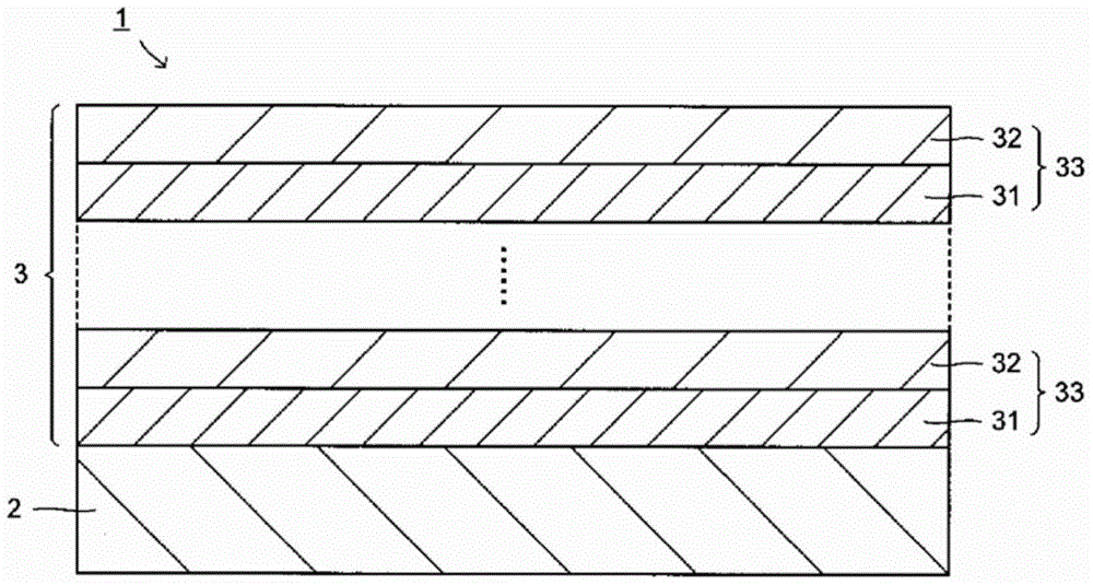
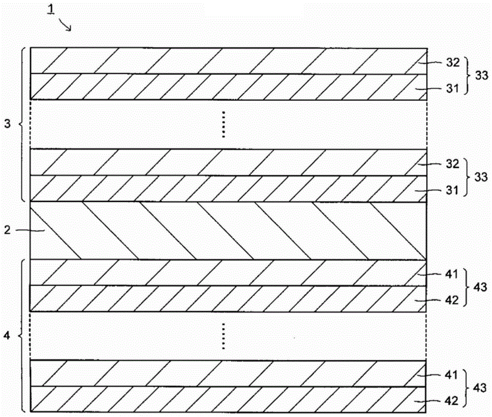
[0070] On one side surface of a soda glass plate with a thickness of 1mm as the transparent substrate 2, as shown in Tables 1 to 3, TiO as the high refractive index layer 31 2 film and SiO as low refractive index layer 32 2 The films are stacked alternately to form the first dielectric multilayer film 3 . In addition, on the other surface of the transparent substrate 2, as shown in Tables 4 to 6, TiO as the high refractive index layer 41 2 film and SiO as low refractive index layer 42 2 The films are laminated alternately to form the second dielectric multilayer film 4, and the optical component 1 is produced.
[0071] It should be noted that for the first dielectric multilayer film 3, the total number of layers obtained by combining the high refractive index layer 31 and the low refractive index layer 32 is 76, that is, the total number of layers of the unit refractive index layer 33 is 38, satisfying n H d H / n L d L The number of layers 33 with a unit refractive index...
Embodiment 2)
[0105] On one surface of a soda glass plate with a thickness of 1 mm as the transparent substrate 2, as shown in Table 13, TiO as the high refractive index layer 31 2 film and SiO as low refractive index layer 32 2 The films are laminated alternately to form the first dielectric multilayer film 3, and the optical component 1 is produced.
[0106] It should be noted that for the first dielectric multilayer film 3, the total number of layers obtained by combining the high refractive index layer 31 and the low refractive index layer 32 is 30, that is, the total number of layers of the unit refractive index layer 33 is 15, satisfying n H d H / n L d L The number of layers 33 with a unit refractive index ≥3 is 13, satisfying n H d H / n L d L The number of layers 33 with a unit refractive index of ≥5 is 12, satisfying 5≤n H d H / n L d L The number of layers 33 with a unit refractive index of ≤8 is 12, and the average n H d H / n L d L is 5.5, the average optical film t...
Embodiment 3)
[0113] On one surface of the near-infrared cut filter glass (NF-50 glass manufactured by Asahi Glass Co., Ltd., glass thickness: 0.3 mm) as the transparent substrate 2, as shown in Tables 14 to 16, the high refractive index layer 31 TiO 2 film and SiO as low refractive index layer 32 2 The films are stacked alternately to form the first dielectric multilayer film 3 . In addition, on the other side surface of the transparent substrate 2, as shown in Table 17, TiO as the high refractive index layer 41 2 film and SiO as low refractive index layer 42 2 The films are laminated alternately to form the second dielectric multilayer film 4, and the optical component 1 is produced.
[0114] It should be noted that for the first dielectric multilayer film 3, the total number of layers obtained by combining the high refractive index layer 31 and the low refractive index layer 32 is 76, that is, the total number of layers of the unit refractive index layer 33 is 38, satisfying n H d H...
PUM
 Abstract
Description
Claims
Application Information
 - R&D
- Intellectual Property
- Life Sciences
- Materials
- Tech Scout
- Unparalleled Data Quality
- Higher Quality Content
- 60% Fewer Hallucinations
Browse by: Latest US Patents, China's latest patents, Technical Efficacy Thesaurus, Application Domain, Technology Topic, Popular Technical Reports.
© 2025 PatSnap. All rights reserved.Legal|Privacy policy|Modern Slavery Act Transparency Statement|Sitemap|About US| Contact US: help@patsnap.com


