Communication path switching method, system and device
A communication path and path technology, applied in the field of communication, can solve problems such as data service continuity cannot be guaranteed
- Summary
- Abstract
- Description
- Claims
- Application Information
AI Technical Summary
Problems solved by technology
Method used
Image

Examples
Embodiment 1
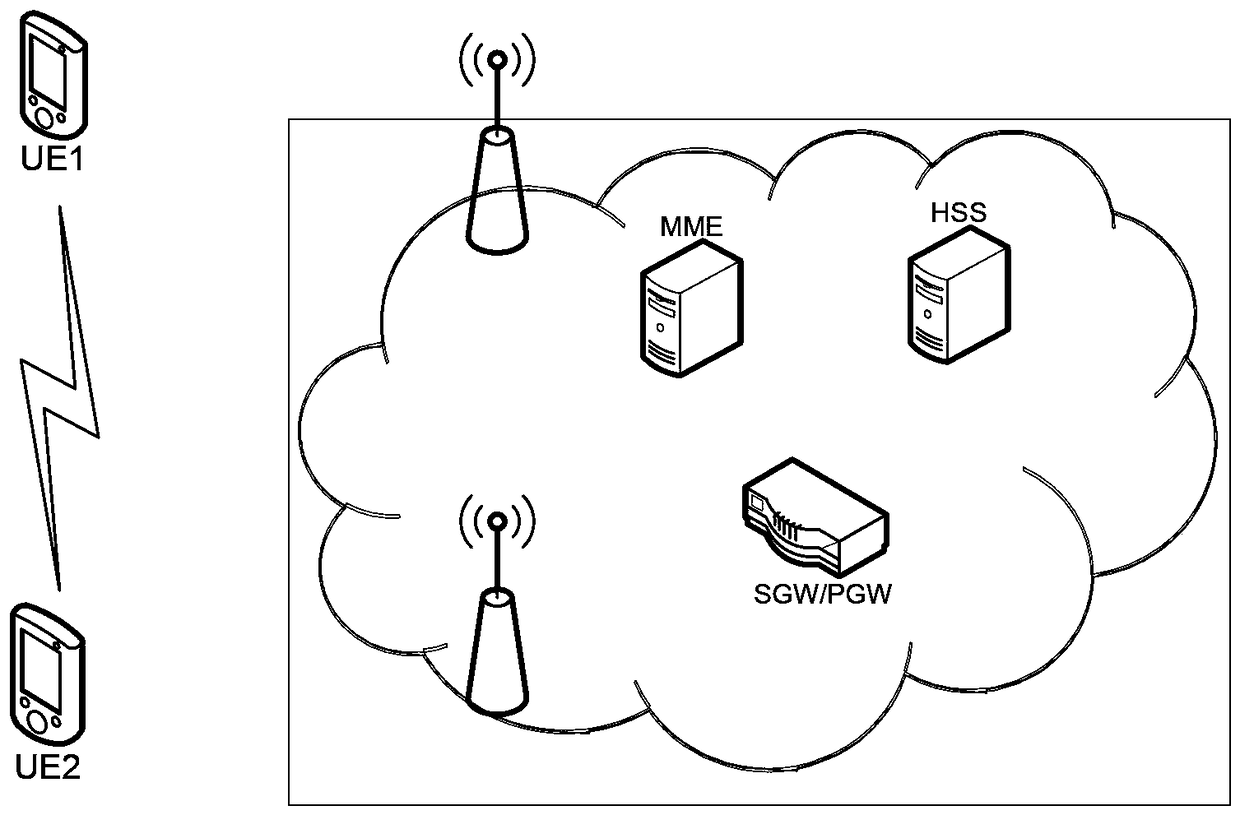
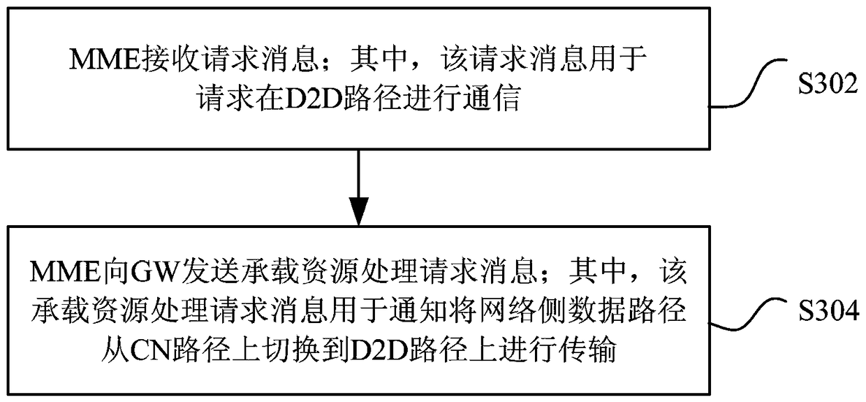
[0096] This embodiment introduces one of the implementation methods for switching services from the CN path to the D2D path. The application scenario of this embodiment is that UE1 and UE2 have established a core network data connection. When they are close to each other, the data detoured from CN Can be passed from the local connection path. Figure 4 is a flow chart of the first implementation of switching from a CN path to a D2D path according to an embodiment of the present invention, as shown in Figure 4 As shown, the process includes the following steps (step S402-step S426):
[0097] In step S402, the two UEs complete the discovery process with each other, and this process may depend on the existing D2D discovery process. Or the two users find that they are very close to each other and issue instructions to the terminal, so that it may not be necessary to execute the D2D discovery process between the two terminals or the terminal and the network in this step.
[0098...
Embodiment 2
[0112] This embodiment introduces the second implementation method of switching services from the CN path to the D2D path. Figure 5 It is a flow chart of the second implementation of switching from a CN path to a D2D path according to an embodiment of the present invention. The application scenario of this embodiment is similar to that of Embodiment 1, and the implementation is also similar. The difference lies in the stage of UE requesting resources. There are some differences, that is, step S504-step S512 is different from step S406-step S412 in the first embodiment, and other steps are similar, such as Figure 5 As shown, the process includes the following steps (step S502-step S526):
[0113] In step S502, the two UEs complete the discovery process with each other, and this process may depend on the existing D2D discovery process. Or the two users find that they are very close to each other and issue instructions to the terminal, so that it may not be necessary to execut...
Embodiment 3
[0121] This embodiment introduces the third implementation method of switching services from the CN path to the D2D path. Figure 6 is a flow chart of the third implementation mode of switching from a CN path to a D2D path according to an embodiment of the present invention. The application scenario of this embodiment is similar to that of Embodiment 1, for example Figure 6 As shown, the process includes the following steps (step S602-step S628):
[0122] In step S602, the two UEs complete the discovery process with each other, and this process may depend on the existing D2D discovery process. During this process, UE1 and UE2 need to go to the eNB for identity verification respectively, so as to ensure that the two UEs can communicate with each other.
[0123] In step S604, the eNB receives a verification request from UE1 and / or UE2, and the request needs to carry identifications of each other. The eNB associates the contexts of the two users according to the locally stored...
PUM
 Abstract
Description
Claims
Application Information
 - R&D
- Intellectual Property
- Life Sciences
- Materials
- Tech Scout
- Unparalleled Data Quality
- Higher Quality Content
- 60% Fewer Hallucinations
Browse by: Latest US Patents, China's latest patents, Technical Efficacy Thesaurus, Application Domain, Technology Topic, Popular Technical Reports.
© 2025 PatSnap. All rights reserved.Legal|Privacy policy|Modern Slavery Act Transparency Statement|Sitemap|About US| Contact US: help@patsnap.com