Method and system for stable phase transmission of radio frequency signal through optical fiber

A radio frequency signal and phase-stable transmission technology, applied in the field of microwave photonics, can solve the problems of high implementation cost and complex system operation, and achieve the effects of simple structure, low system loss, and significant phase-stabilization effect.

Active Publication Date: 2016-04-06
NANJING UNIV OF AERONAUTICS & ASTRONAUTICS
View PDF4 Cites 0 Cited by
  • Summary
  • Abstract
  • Description
  • Claims
  • Application Information

AI Technical Summary

Problems solved by technology

The currently reported phase-stable transmission technology based on the frequency mixing method uses multi-stage (more than 3) mixing, which requires multiple mixers, electrical amplifiers, electrical filters, and multiple phase-synchronized microwave sources. The system operation is complex and difficult to implement. The cost is high, and more importantly, the output of this system is an intermediate frequency signal, not the original RF signal received by the sending end (Z.Wu,Y.Dai,F.Yin,K.Xu,J.Li,andJ.Lin," Stable radio frequency phase delivery by rapid and endless post error cancellation," Opt. Lett. , vol.38, no.7, pp.1098-1100, 2013.)

Method used


Image

  • Method and system for stable phase transmission of radio frequency signal through optical fiber
  • Method and system for stable phase transmission of radio frequency signal through optical fiber
  • Method and system for stable phase transmission of radio frequency signal through optical fiber

Examples


Embodiment Construction

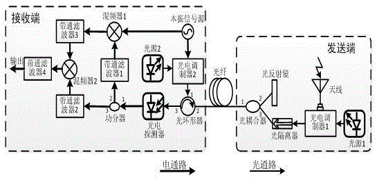
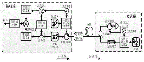
[0019] The technical scheme of the present invention is described in detail below in conjunction with accompanying drawing:

[0020] The basic idea of ​​the present invention is: the transmission delay after the local oscillator signal generated by the receiving end is transmitted back and forth in the optical fiber is twice the delay of the one-way transmission of the signal transmitted by the sending end in the optical fiber, and the local oscillator signal source generates The frequency of the RF signal is half of the frequency of the signal received by the antenna, so the phase jitter of the two signals after transmission is the same, and the phase jitter of the two signals can be offset by frequency mixing, thereby obtaining a phase-stable RF signal after optical fiber transmission. Specifically, the method adopted in the present invention is as follows: the transmitting end performs optical modulation on the radio frequency signal to be transmitted and then transmits it t...


PUM


Abstract

The invention discloses an RF signal optical fiber phase-stabilized transmission method. The method specifically includes the steps that a sending end carries out light modulation on RF signals needing to be transmitted, and then transmits the RF signals to a receiving end through an optical fiber; the receiving end carries out light modulation on local oscillator signals and transmits the local oscillator signals to the sending end through the optical fiber, and the sending end sends received light modulation signals of the local oscillator signals back to the receiving end through the optical fiber, wherein the frequency of the local oscillator signals is half that of the RF signals needing to be transmitted; the receiving end carries out modulation on light signals input in the optical fiber to obtain mixed RF signals, and then extracts first signals and second signals from the mixed RF signals respectively, wherein the frequency of the first signals is equal to that of the RF signals needing to be transmitted, and the frequency of the second signals is equal to that of the local oscillator signals; up-conversion is carried out on the first signals and the local oscillator signals, and then down-conversion is carried out on the obtained signals and the second signals to finally obtain the transmission RF signals transmitted in a phase-stabilized mode. The invention further discloses an RF signal optical fiber phase-stabilized transmission system. Quality of phase-stabilized transmission of the signals is high and the RF signal optical fiber phase-stabilized transmission system is simple in structure.

Description

technical field [0001] The invention relates to a method and system for stable phase transmission of radio frequency signal optical fiber, in particular to a method and system for stable phase transmission of radio frequency signal optical fiber based on frequency mixing and elimination method, belonging to the technical field of microwave photonics. Background technique [0002] Phase-stable transmission technology has important applications in the fields of radio astronomy, distributed synthetic aperture radar, high-precision standard clock distribution, particle accelerators, and global navigation satellite system (GNSS) multi-antenna receivers that use carrier phase for positioning and navigation. . Traditionally, the use of cables for radio frequency signal transmission is difficult for long-distance radio frequency signal transmission due to its disadvantages such as high loss, high price, and large size. Optical fiber has the advantages of low transmission loss, anti...

Claims


Application Information

Patent Timeline
Patent Type & Authority Patents(China)
IPC IPC(8): H04B10/2507H04B10/2575
Inventor 张方正魏娟潘时龙宋希希薛敏周永刚
Owner NANJING UNIV OF AERONAUTICS & ASTRONAUTICS
Why Eureka
Try Eureka