
Fan pneumatic conveying and cleaning and settling system

A technology of pneumatic conveying and fan, applied in the direction of conveyor, transportation and packaging, conveying bulk materials, etc., can solve the problems of impeller blade wear, reduce the service life of fan, complex process, achieve small size and improve normal operation efficiency , the effect of reducing manufacturing costs

Inactive Publication Date: 2016-02-10
李通
View PDF7 Cites 0 Cited by
  • Summary
  • Abstract
  • Description
  • Claims
  • Application Information

AI Technical Summary

Problems solved by technology

[0003] In order to realize the smooth operation of the system, most of the processes use negative pressure to feed the material, and then clean it after falling into the cleaning machine. Due to the poor air closure of the air locker, it is easy to wear and block during production, and the material contains more Dust, gravel and soft substances (such as fibers) are likely to cause wear of the impeller blades under the action of the fan-induced wind, and soft impurities are easy to wrap around the impeller blades, causing the static balance of the impeller to be out of balance, causing the fan to vibrate and reducing the service life of the fan , affect the normal production, so that the normal operation rate of the process system is not high, the operating cost is high, the process is complicated, and the operation labor intensity is high, etc.

Method used


Image

  • Fan pneumatic conveying and cleaning and settling system
  • Fan pneumatic conveying and cleaning and settling system
  • Fan pneumatic conveying and cleaning and settling system

Examples


Embodiment Construction

[0033] In order to make the purpose of the present invention, technical solutions and advantages more clearly understood, the present invention will be further described in detail below in conjunction with the accompanying drawings

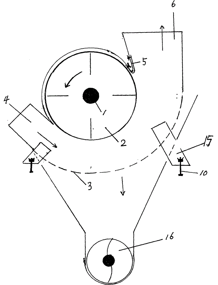
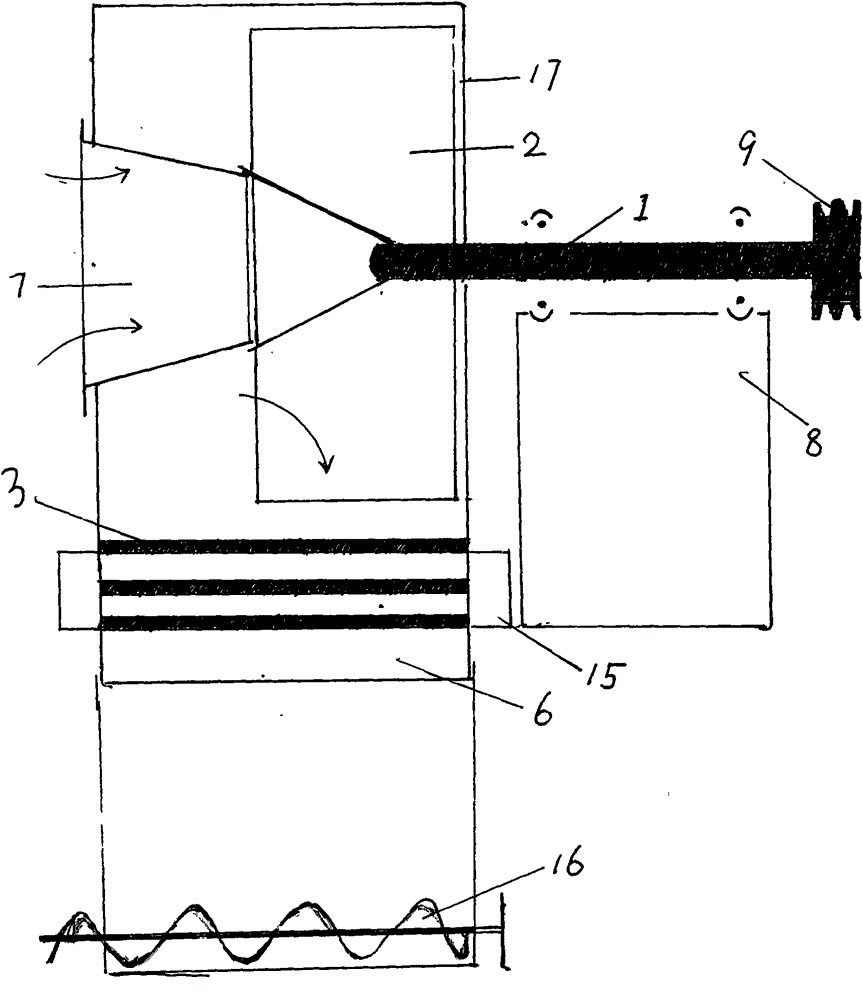
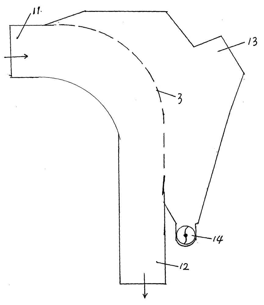
[0034] The ventilator pneumatic conveying and cleaning and settling system of the present invention changes the structure of the existing ventilator, and sets a radial air inlet (material) port at an appropriate position of the casing, cleans the combination (or seals the arc-shaped plate), and installs a miscellaneous discharge at its lower part The auger, set the air tongue and its adjusting plate at the position of the fan air tongue, set the cleaning combination (or sealing arc plate) in the settlement part, the suction port of the dust exhaust pipe, the miscellaneous auger, etc., and use the impeller to drive Next, the negative pressure generated at the radial air inlet (material) port, the positive pressure generated at the cleaning combinati...


PUM


Abstract

The invention provides a pneumatic conveying, cleaning and settling system of a ventilator. A radial air inlet / feeding port (4) and a cleaning combining device (or an arc sealing plate) (3) are arranged at appropriate positions of a machine shell of the ventilator, an air tongue and an adjusting plate (5) of the air tongue are arranged at the position of the air tongue, an impurity discharging auger (16) is arranged at the outer side of the machine shell (17) and the lower portion of the cleaning combining device (3), and the cleaning combining device (or the arc sealing plate) (3), a dust exhaust air induction pipe suction port (13) and an impurity discharging auger or impurity sucking port (14) are arranged at a settling part. The pneumatic conveying, cleaning and settling system of the ventilator changes the structure of an existing ventilator, air power and inertial centrifugal force formed by high-speed rotation of an impeller can make materials directly enter the ventilator through the radial air inlet / feeding port, the materials are cleaned and conveyed by the cleaning combining device or conveyed by the arc sealing plate, and are discharged through an outlet of the ventilator, the purposes of conveying and cleaning the materials are achieved, secondary cleaning and conveying of the settling part enable the materials to be cleaner, or the materials output through positive pressure of the existing ventilator enter the settling part for cleaning and separation, and a certain cleaning effect can also be achieved.

Description

technical field [0001] The invention relates to the field of ventilators, in particular to a ventilator pneumatic conveying machine integrating the ventilator pneumatic conveying cleaning and settling systems. Background technique [0002] In pneumatic conveying, at present, under the action of the induced draft of the fan, the material enters the separator through the air net, and the air flow of the separator is separated from the material, and the closed air of the lower air locker blocks the air flow and its rotation to realize the material After settling, it enters the next process, and then the air is induced by the fan, the separator is separated, and the air locker is unloaded to realize the secondary separation and settlement, and then enters the next process for cleaning or transportation. [0003] In order to realize the smooth operation of the system, most of the processes use negative pressure to feed the material, and then clean it after falling into the cleani...

Claims


Application Information

Patent Timeline
Patent Type & Authority Patents(China)
IPC IPC(8): B65G53/24B65G53/34B65G53/48B65G53/46B65G53/60
Inventor 李通
Owner 李通
Learn More