
Data transmitting system of digital medical imaging device based on optical fiber communications

A technology of data transmission system and medical imaging, applied in the field of data transmission system, can solve the problems such as the reduction of data rate, the inability of Gigabit Ethernet interface to meet the real-time data transmission requirements of image sensors, and the reduction of imaging resolution.

Inactive Publication Date: 2014-04-09
TIANJIN UNIV
View PDF3 Cites 7 Cited by
  • Summary
  • Abstract
  • Description
  • Claims
  • Application Information

AI Technical Summary

Problems solved by technology

When transmitting data through Gigabit Ethernet, due to the overhead of network protocols and the delay of hardware processing data packets, generally only stable and reliable data transmission of about 600 Mbps can be achieved. It can be seen that the Gigabit Ethernet interface cannot meet the real-time requirements of this image sensor. Data Transfer Requirements
The C10500D-42 sensor newly launched by HAMAMATSU is equipped with a Gigabit Ethernet interface, but the sensor has only one port to output data, and the highest data rate is reduced to 420Mbps, at the cost of reducing the imaging resolution (the resolution of C10502D is 2268x60, The resolution of C10500D-42 is 1480x60)

Method used


Image

  • Data transmitting system of digital medical imaging device based on optical fiber communications
  • Data transmitting system of digital medical imaging device based on optical fiber communications
  • Data transmitting system of digital medical imaging device based on optical fiber communications

Examples


Embodiment Construction

[0027] A data transmission system for a digital medical imaging device based on optical fiber communication of the present invention will be described in detail below with reference to the embodiments and the accompanying drawings.

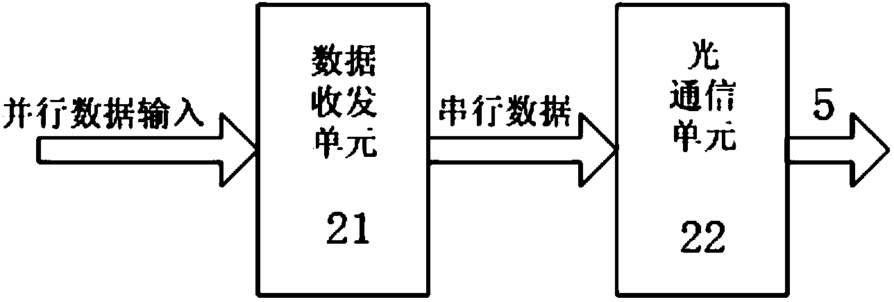
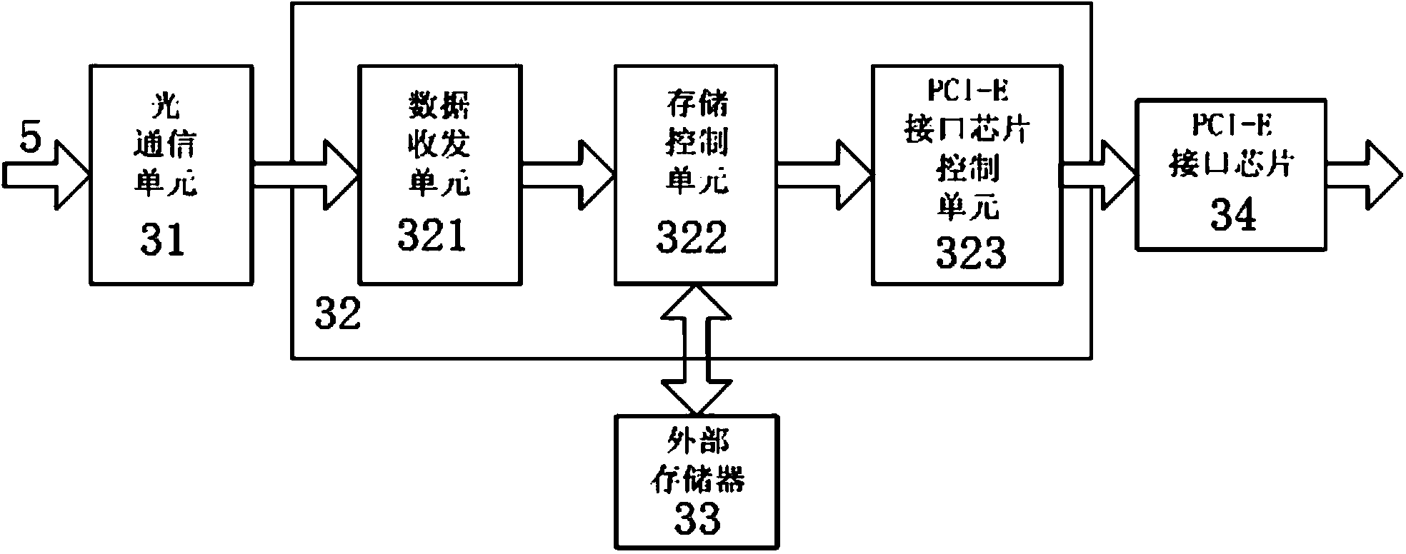
[0028] Such as figure 1 As shown, the data transmission system of a digital medical imaging device based on optical fiber communication in the present invention mainly completes the transmission of digital image data generated by a flat-panel X-ray sensor. It includes a flat-panel X-ray sensor 1 for receiving X-rays. In this embodiment, the flat-panel X-ray sensor adopts the C10502D flat-panel X-ray sensor of HAMAMATSU Company. The output end of the flat panel X-ray sensor 1 is connected to the data sending module 2, the data sending module 2 is connected to the data acquisition module 3 through the optical fiber 5, and the data acquisition module 3 is connected to the computer 4 through the PCI-E interface. The data sending module forwards the d...


PUM


Abstract

The invention discloses a data transmitting system of a digital medical imaging device based on optical fiber communications. The data transmitting system is provided with a panel X-ray sensor used for receiving X-rays, wherein the output end of the panel X-ray sensor is connected with a data sending module; the data sending module is connected with a data collection module through optical fibers; the data collection module is connected with a computer through a PCI-E interface. The data sending module is provided with a data receiving and sending unit and a first optical communication unit which are connected in sequence; the signal input end of the data receiving and sending unit is connected with the signal output end of the panel X-ray sensor; the signal output end of the first optical communication unit is connected with the data collection module through optical fibers. The data collection module is provided with a second communication unit, a data collection and storage unit, a PCI-E interface chip and an external storage which are connected in sequence; a storage and control unit is connected with the external storage. According to the data transmitting system of the digital medical imaging device based on the optical fiber communications, real-time and non-compression transmission of high-resolution-ratio digital medical images from an image sensor to a computer is achieved, and the real-time and high-speed non-compression data transmission between the medical imaging device and the external computer is achieved.

Description

technical field [0001] The invention relates to a data transmission system of digital medical imaging equipment. In particular, it relates to a data transmission system of digital medical imaging equipment based on optical fiber communication. Background technique [0002] Digital medical imaging equipment usually consists of image sensors, data sending modules, data receiving modules, data processing and display modules. The common form is that medical imaging equipment includes image sensors and data sending modules, and external computers include data receiving modules and data processing modules. Like the display module, the medical imaging device transmits data to the computer through some kind of high-speed data interface. [0003] With the improvement of imaging resolution and frame rate of image sensors, the amount of raw image data obtained by imaging devices is increasing. The image output methods of imaging devices can be divided into two categories: compression...

Claims


Application Information

Patent Timeline
IPC IPC(8): A61B6/00H04B10/25
Inventor 吕卫褚晶辉葛长宽娄新磊
Owner TIANJIN UNIV
Learn More