
A Tooling for Trimming Pins in Ceramic Pillar Grid Arrays

A ceramic column grid array and tooling technology, which is applied in the manufacture of electrical components, electrical solid devices, semiconductor/solid devices, etc., can solve problems such as oxidation and pin skew, and achieve the effect of improving the accuracy and quality of orthopedics

Active Publication Date: 2016-02-10
BEIJING RES INST OF TELEMETRY +1
View PDF3 Cites 0 Cited by
  • Summary
  • Abstract
  • Description
  • Claims
  • Application Information

AI Technical Summary

Problems solved by technology

[0004] The purpose of the present invention is to propose a tool for trimming the pins in the ceramic column grid array in order to overcome the problem of skewing or oxidation of the pins in the ceramic column grid array in the prior art

Method used


Image

  • A Tooling for Trimming Pins in Ceramic Pillar Grid Arrays
  • A Tooling for Trimming Pins in Ceramic Pillar Grid Arrays
  • A Tooling for Trimming Pins in Ceramic Pillar Grid Arrays

Examples


Embodiment

[0025] A tool for trimming pins in a ceramic column grid array, the tool includes a grinding tool and an orthopedic tool;

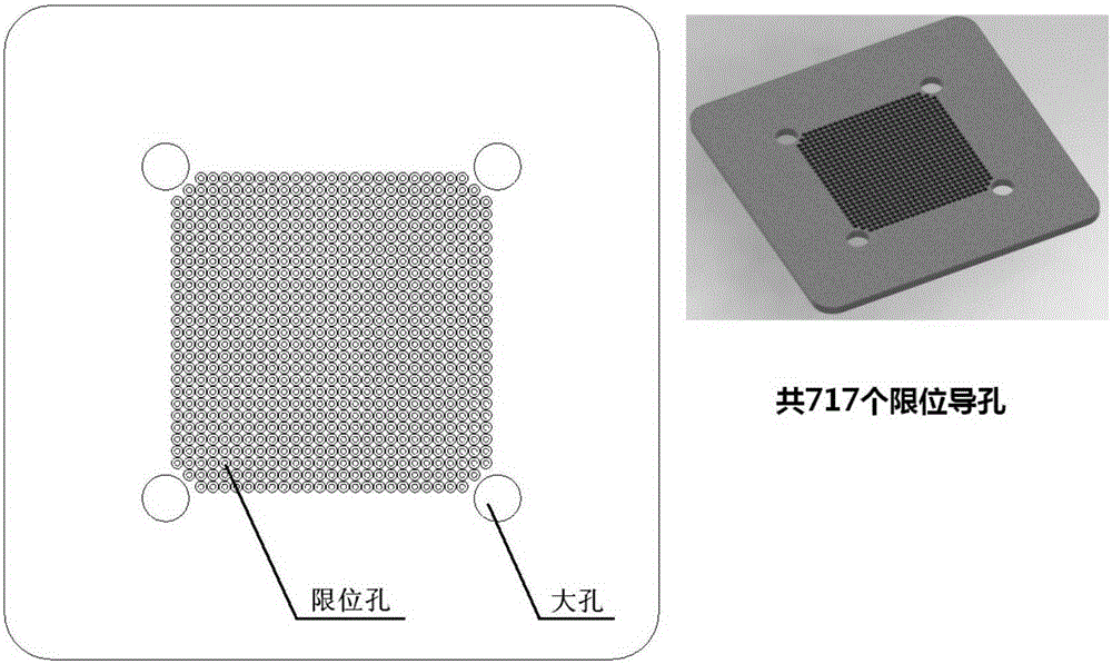
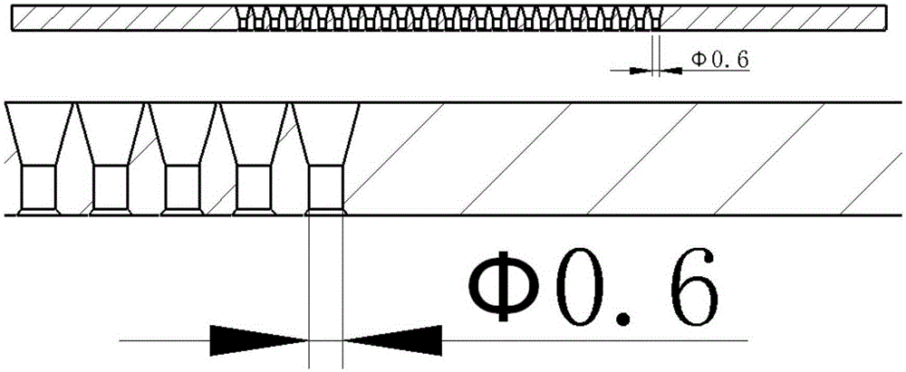
[0026] Such as figure 1 with figure 2 As shown, the orthopedic tooling is an orthopedic clamp, and there are 717 limit holes distributed in its center, and the distribution of the limit holes matches the position of the pins in the ceramic column grid array; the diameter of the limit holes is 0.6mm, 0.7 mm and 0.8mm, the distance between the limit holes is 1.27mm, one side of the limit hole is drilled with a 15° guide hole, and the depth is half of the overall depth of the limit hole;

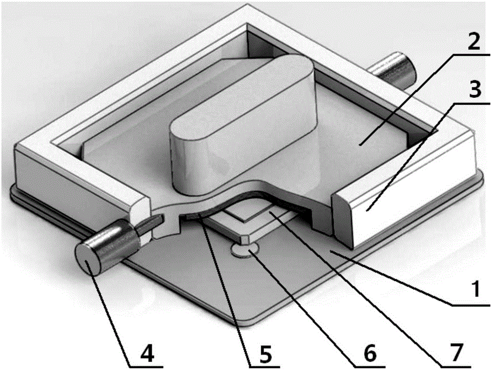
[0027] Such as image 3 with Figure 4 As shown, the grinding tooling includes a pressing block handle 2, a limit card plate combination, a locking pin 4, a sponge cushion 5 and an adjusting gasket 6;

[0028] The limit card plate combination includes a positioning frame 3 and a limit card plate 1;

[0029] There is a square working area in the center of the limit ca...


PUM


Abstract

The invention relates to a tooling for reconditioning a pin in a ceramic column grid array (CCGA), belonging to the technical field of the CCGA. In the tooling for removing an oxidized layer, the exposure quantity of the pin of the CCGA device, relative to a clamping plate, can be adjusted by an adjusting washer, and is properly controlled to be about 0.1mm. An operator slightly grinds special abrasive paper stably by holding a pressure block handle, so as to achieve the purpose of removing the oxidized layer on the welded surface of the pin. The tooling is convenient to operate in the overall process, good in grinding effect, and capable of improving the overall planeness of the welded surface while the oxidized layer on the welded surface of the pin is removed.

Description

technical field [0001] The invention relates to a tool for trimming pins in a ceramic column grid array, belonging to the technical field of ceramic column grid arrays. Background technique [0002] Ceramic Column Grid Array (CCGA) packages are widely used in electronic products such as military and aerospace due to their high-density I / O, high reliability, and excellent electrical and thermal performance. But at the same time, due to its special structural characteristics, the welding process technology of CCGA devices has certain difficulties. [0003] CCGA's single board assembly adopts standard surface mount equipment and process flow, and goes through the steps of printed board cleaning, solder paste leakage, patch, reflow soldering, cleaning and testing. Before the assembly process, special attention should be paid to the storage and protection of CCGA devices. Generally speaking, CCGA device suppliers will provide special device protection devices, mostly black elec...

Claims


Application Information

Patent Timeline
Patent Type & Authority Patents(China)
IPC IPC(8): H01L21/67
CPCH01L24/49
Inventor 张瑶何伟严曦光曾令迪王慧玲
Owner BEIJING RES INST OF TELEMETRY
Learn More