Surgical Drills
A technology for surgery and grinding drills, which is applied in the fields of surgery and medical science, can solve the problems of single use of grinding drills, large instantaneous grinding amount, fixed grinding position direction, etc., and achieves simple structure, good safety, Highly stable effect
- Summary
- Abstract
- Description
- Claims
- Application Information
AI Technical Summary
Problems solved by technology
Method used
Image
Examples
Embodiment 1
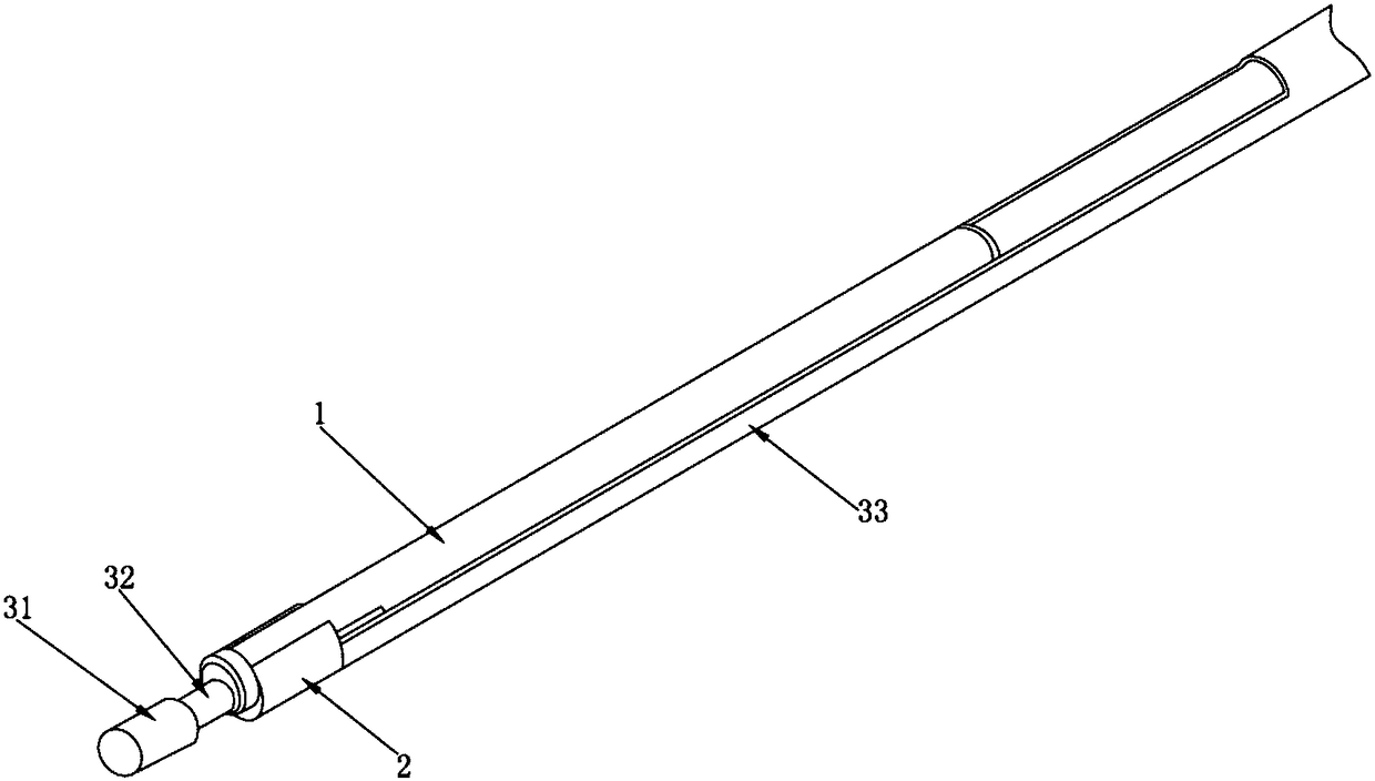
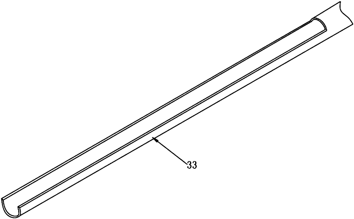
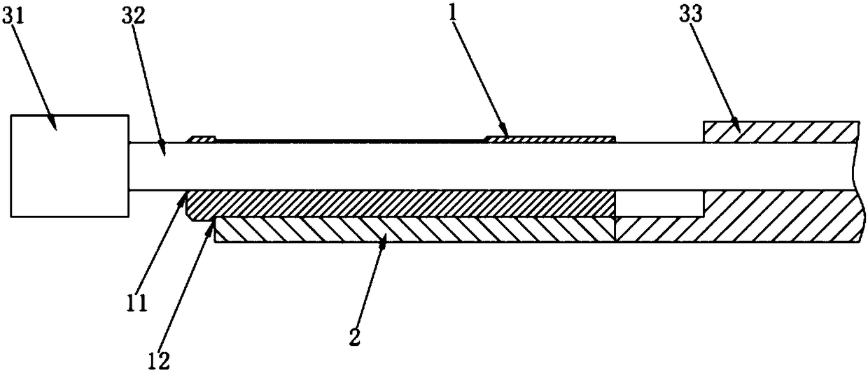
[0033] Depend on figure 1 , figure 2 and image 3 As shown, the present invention is composed of a grinding head 31 and a knife tube 33, etc., the grinding head 31 is provided with a grinding handle 32, and the end of the knife tube 33 near the grinding head 31 is provided with an inner support body 1 and an outer support body 2 The double-layer structure, the grinding handle 32 passes through the inner support body 1, the inner support body 1 is provided with the first eccentric hole 11, and the grinding handle 32 is set in the first eccentric hole 11; the outer The support body 2 is provided with a second eccentric hole 21, the inner support body 1 is sleeved in the second eccentric hole 21, the outer circle of the inner support body 1 and the inner diameter of the second eccentric hole 21 cooperate; the outer support body A section of opening is provided on the side of the body 2 close to one end of the grinding head 31 , and the second eccentric hole 21 is connected thr...
Embodiment 2
[0037] Such as figure 1 , figure 2 and Figure 4 As shown, the difference from Example 1 is that the inner support body 1 is provided with a first oblique hole 12, and the grinding handle 32 is penetrated in the first oblique hole 12; the outer support body 2 is provided with a second oblique hole 22. The inner support body 1 is sleeved in the second slanted hole 22, and the outer circle of the inner support body 2 and the inner diameter of the second slanted hole 22 match.
[0038] When in use, the design of the inclined hole can make the grinding handle 32 with soft material adjustable in direction, and at the same time make the protruding grinding head 31 have a parallel or oblique grinding angle, so that the space can be used in a wider range. Two support bodies The outer diameter of the first slanted hole 12 and the inner diameter of the second slanted hole 22 cooperate with each other to meet the rotation requirements between the two supports, avoid interference durin...
Embodiment 3
[0040] Such as figure 1 , figure 2 and Figure 5 As shown, the difference from Example 1 is that the inner wall of the opening section of the outer support body 2 is provided with a slope structure, and one side of the outer wall of the inner support body 1 is provided with a slope structure that is compatible with the slope structure. , the relative movement between the inclined plane and the inclined plane structure.
[0041]During use, under the action of external force, the outer support body 2 can drive the inner support body 1 to rotate, and the first eccentric hole 11 on the inner support body 1 can rotate with the grinding handle 32, that is, the grinding head 31 also rotates. During operation, the axial position of the grinding handle 32 moves in parallel with or away from the axial position of the outer support body 12, thereby increasing the grinding range of the grinding head 31; in addition to eccentric rotation, the inner support body 1 can also Move axially ...
PUM
 Abstract
Description
Claims
Application Information
 - R&D
- Intellectual Property
- Life Sciences
- Materials
- Tech Scout
- Unparalleled Data Quality
- Higher Quality Content
- 60% Fewer Hallucinations
Browse by: Latest US Patents, China's latest patents, Technical Efficacy Thesaurus, Application Domain, Technology Topic, Popular Technical Reports.
© 2025 PatSnap. All rights reserved.Legal|Privacy policy|Modern Slavery Act Transparency Statement|Sitemap|About US| Contact US: help@patsnap.com


