Rigidity-variable positioning device for bogie axle box of railway vehicle

A bogie shaft and railway vehicle technology, which is applied in the field of variable stiffness positioning devices for railway vehicle bogie axle boxes, can solve the problems of reducing the function of the axle box elastic suspension device, complex structural design, poor assembly versatility, etc., and achieves improved vehicle dynamics. The effect of performance, guaranteeing operation safety, and easy disassembly and maintenance

Active Publication Date: 2014-04-02
CRRC YANGTZE CO LTD
View PDF6 Cites 8 Cited by
  • Summary
  • Abstract
  • Description
  • Claims
  • Application Information

AI Technical Summary

Problems solved by technology

[0006] At present, improving the critical running speed of the vehicle on a straight line and improving the passing performance of the vehicle on a curve are a pair of contradictions, and it is difficult to give consideration to each other in the specific design of the elastic suspension device of the vehicle bogie axle box
This is because the existing two main axlebox elastic suspension devices cannot meet the above requirements at the same time: one is a vertical elastic device arranged between the top surface of the axlebox bearing saddle and the bottom surface of the side frame pedestal. It has a certain effect on the vertical vibration reduction of the bogie, but there is a rigid hard contact between the axle box saddle and the side of the side frame pedestal without any buffer device, not only has a relatively low effect on the lateral vibration and longitudinal vibration of the bogie Poor, and the structural design is relatively complex, parameter matching is very difficu...

Method used


Image

  • Rigidity-variable positioning device for bogie axle box of railway vehicle
  • Rigidity-variable positioning device for bogie axle box of railway vehicle
  • Rigidity-variable positioning device for bogie axle box of railway vehicle

Examples


Embodiment 1

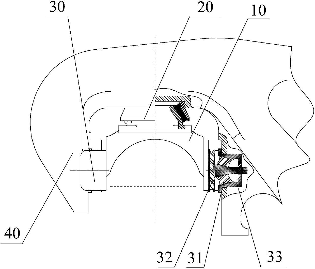
[0045] Such as figure 1 As shown, a kind of railway vehicle bogie axle box variable stiffness positioning device of the present invention mainly consists of a vertical elastic body 20 arranged between the top surface of the axle box bearing saddle 10 and the bottom surface of the side frame pedestal 40, and the The axle box bearing saddle 10 is combined with the longitudinal elastic body 30 between the front and rear sides of the side frame pedestal 40 . The longitudinal elastic body 30 has a small stiffness elastic element 31 and a large stiffness elastic element 32, the small stiffness elastic element 31 is arranged in the elastic body pre-compression device 33, and is connected in series with the large stiffness elastic element 32 under the action of the precompression load F1 layout.

[0046] Such as figure 2 As shown, the large rigidity elastic element 32 has an elastic rubber base layer 32a, and the elastic rubber base layer 32a is sandwiched between two metal bearing...

Embodiment 2

[0056] Such as Figure 7 As shown, another railway vehicle bogie axle box variable stiffness positioning device of the present invention, its overall structure is basically the same as that of Embodiment 1, and the difference is still that it is pre-determined by a small stiffness elastic element 31, a large stiffness elastic element 32 and an elastic body. On the fourth type of longitudinal elastic body 30 composed of compression device 33 .

[0057] Such as Figure 8 As shown, in the fourth longitudinal elastic body 30, its high-rigidity elastic element 32 has an elastic rubber base layer 32a, and the elastic rubber base layer 32a is sandwiched between two metal bearing plates 32b and vulcanized into an integral body with them.

[0058] Its elastic body pre-compression device 33 has a rigid outer cover 33a, and the rigid outer cover 33a is axially provided with a guide positioning screw 33b, and one end of the guide positioning screw 33b stretches out from the opening of th...


PUM


Abstract

A rigidity-variable positioning device for a bogie axle box of a railway vehicle comprises a vertical elastomer and longitudinal elastomers. The vertical elastomer is arranged between the top face of an axle box bearing saddle and the bottom face of a side-rack guide frame. The longitudinal elastomers are arranged between the axle box bearing saddle and the front lateral side as well as the back lateral side of the side-rack guide frame respectively. Each longitudinal elastomer at least comprises a low-rigidity elastic element and a high-rigidity elastic element. The low-rigidity elastic elements are arranged in elastomer pre-compressing devices and are connected with the large-rigidity elastic elements in series under the action of pre-compressing loads F1. The longitudinal elastomers have large longitudinal compression rigidity on the condition of small longitudinal deformation and displacement quantity, and can ensure the railway vehicle to have a high snakelike critical speed during linear running to meet the need of accelerated running of the vehicle; the longitudinal rigidity of the longitudinal elastomers starts to decrease on the condition that the longitudinal deformation and displacement quantity reaches a preset level, so that proper horizontal force between wheel tracks when the railway vehicle runs on curved tracks can be guaranteed, and further, safety in curve running of the vehicle is guaranteed.

Description

technical field [0001] The invention relates to the design and manufacturing technology of a railway vehicle bogie, in particular to a variable stiffness positioning device for a railway vehicle bogie axle box. Background technique [0002] A railway vehicle is a special vehicle running on a specially designed track, which can guide itself without controlling the direction when running along the specially designed track. The bogie is one of the most important components on a railway vehicle, it supports the weight of the entire cargo and the weight of the car body itself. Traditional bogies are mostly three-piece structures consisting of two side frames and a bolster. The pedestal frame at both ends of the side frame is installed on the front and rear wheel sets through the axle box bearing saddle and bearing device, and the bolster is composed of The two ends of the car are installed in the central box formed by the side frames through two sets of central spring suspension...

Claims


Application Information

Patent Timeline
IPC IPC(8): B61F5/30
Inventor 严志雄姜瑞金张良威崔红刘凤伟刘文亮伏铁军淡赵军王平平
Owner CRRC YANGTZE CO LTD
Why Eureka
Try Eureka