
Electronic component mounting apparatus

An electronic component installation and electronic component technology, applied in the direction of electrical components, electrical components, etc., can solve the problems of excessive pressing of the suction nozzle, deviation, unstable electronic component installation action, etc., and achieve the effect of stable adsorption

Active Publication Date: 2014-03-26
JUKI CORP
View PDF7 Cites 16 Cited by
  • Summary
  • Abstract
  • Description
  • Claims
  • Application Information

AI Technical Summary

Problems solved by technology

However, even if the load detection unit is provided, there may be cases where the detected load and the actual load deviate, or the suction nozzle is pushed in excessively, or the suction nozzle is separated, and the mounting operation of the electronic component becomes unstable.

Method used


Image

  • Electronic component mounting apparatus
  • Electronic component mounting apparatus
  • Electronic component mounting apparatus

Examples


Embodiment Construction

[0037] Hereinafter, the present invention will be described in detail with reference to the accompanying drawings. In addition, this invention is not limited by the form (henceforth embodiment) for carrying out the following invention. In addition, the constituent elements in the following embodiments include elements that can be easily conceived by those skilled in the art, elements that are substantially the same, and elements within a so-called equivalent range. In addition, components disclosed in the following embodiments may be appropriately combined.

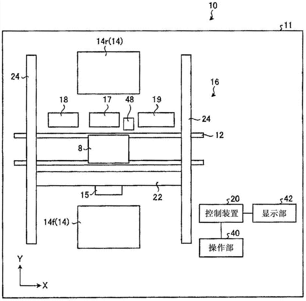
[0038] Hereinafter, embodiments of the electronic component mounting apparatus according to the present invention will be described in detail based on the drawings. In addition, this invention is not limited by this embodiment. figure 1 It is a schematic diagram which shows the schematic structure of an electronic component mounting apparatus.

[0039] figure 1 The illustrated electronic component mounting apparatus 1...


PUM


Abstract

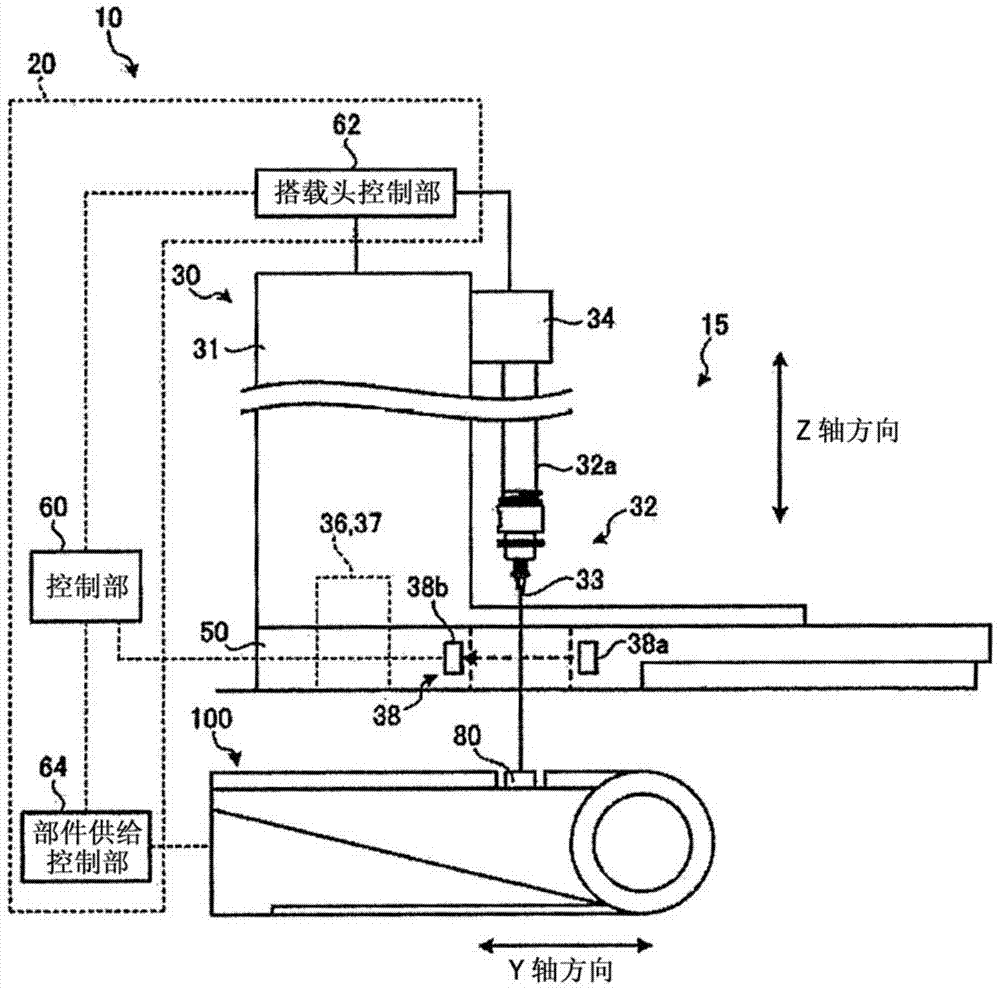
The invention provides an electronic component mounting apparatus, wherein electronic components can be stably absorbed onto a substrate to be mounted. The electronic component mounting apparatus comprises an electronic component feeding unit, a carrying head main body provided with a suction nozzle, a suction nozzle drive part and a carrying head support used for supporting both the suction nozzle and the suction nozzle drive part, a carrying head moving mechanism used for moving the carrying head main body, a load detecting part used for detecting a load generated during the pressing process of the front end of the suction nozzle onto a testing surface, a suction nozzle shape detecting part used for detecting the shape of the suction nozzle, and a control unit used for controlling the operations of all the above parts. The control unit detects the outer shape of the suction nozzle, the absence or presence of a spring and the stroke of the spring by means of the load detecting part and the suction nozzle shape detecting part. Then the detection result is stored as the characteristics of the suction nozzle. Based on the characteristics of the suction nozzle, the control unit controls the suction nozzle drive part to drive the suction nozzle to move up and down.

Description

technical field [0001] The present invention relates to an electronic component mounting device that holds an electronic component with a suction nozzle, moves the electronic component, and mounts the electronic component on a substrate. Background technique [0002] An electronic component mounting apparatus for mounting an electronic component on a substrate has a mounting head provided with a suction nozzle, and the electronic component is held by the suction nozzle and mounted on the substrate. The electronic component mounting device moves the suction nozzle of the mounting head in a direction perpendicular to the surface of the substrate to absorb the components in the electronic component supply device, and then makes the mounting head face to face in a direction parallel to the surface of the substrate. After reaching the mounting position of the suctioned component, the suction nozzle of the mounting head moves in a direction perpendicular to the surface of the subs...

Claims


Application Information

Patent Timeline
IPC IPC(8): H05K13/04
Inventor 恒川祐树
Owner JUKI CORP
Learn More