
Switching power supply over-current protection circuit

An overcurrent protection circuit, switching power supply technology, applied in emergency protection circuit devices, electrical components, etc., can solve problems such as bombing, high impedance, and high power consumption.

Inactive Publication Date: 2014-03-26
SHENZHEN OCEANS KING LIGHTING ENG CO LTD +1
View PDF4 Cites 8 Cited by
  • Summary
  • Abstract
  • Description
  • Claims
  • Application Information

AI Technical Summary

Problems solved by technology

This inductive component presents a large impedance at high frequencies, so it will dissipate a lot of power
As the frequency increases, because the response time required by the pulse width modulation chip from obtaining the feedback signal to outputting the PWM signal is longer, the current flowing through the sampling resistor may not be discharged before the next oscillation cycle arrives, and the sampling resistor withstands The current will become larger and larger, which will cause misoperation of the pulse width modulation chip, and even cause a bombing

Method used


Image

  • Switching power supply over-current protection circuit
  • Switching power supply over-current protection circuit

Examples


Embodiment Construction

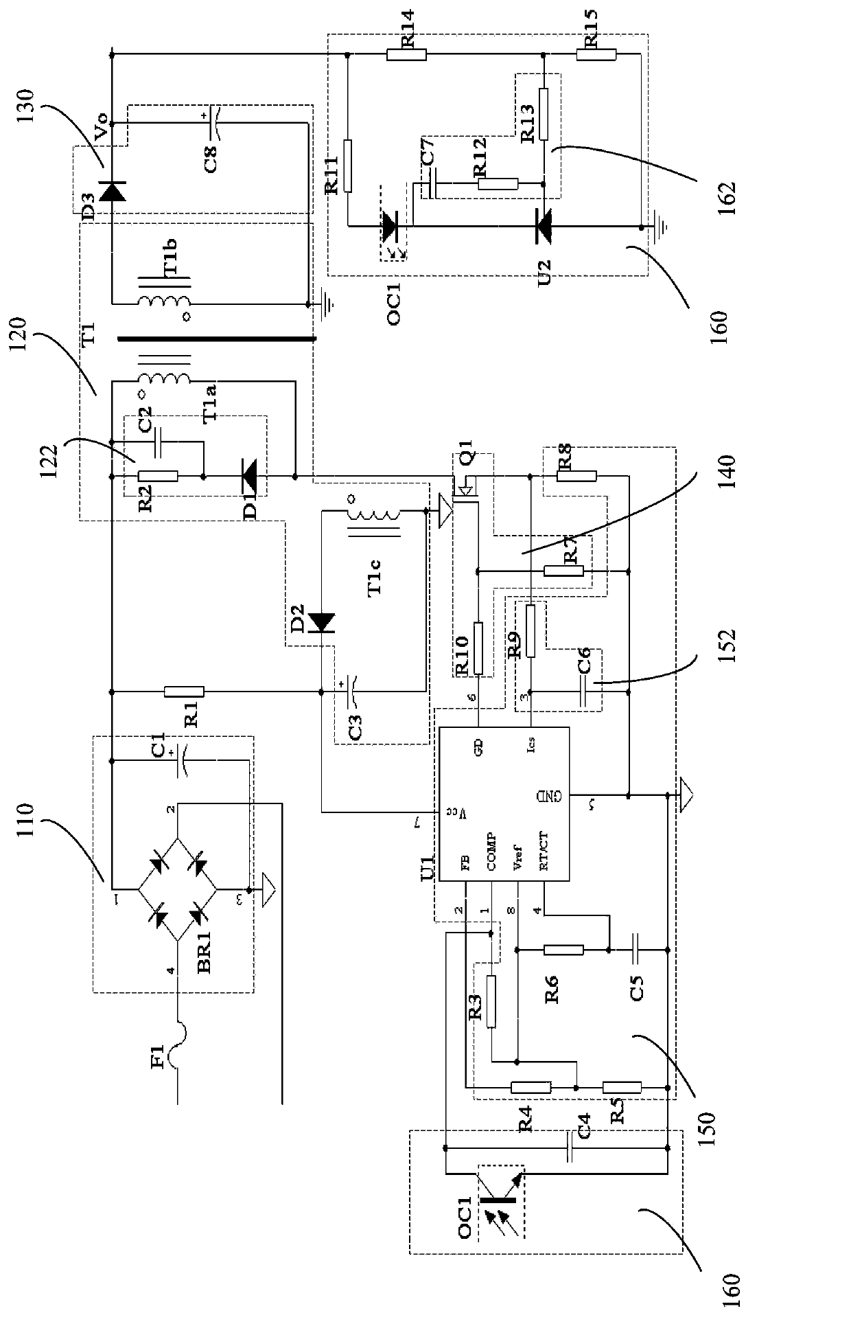
[0019] A switching power supply overcurrent protection circuit, such as figure 1 As shown, it includes an AC rectification and filtering circuit 110 , a transformer 120 , a DC rectification and filtering circuit 130 , a switch circuit 140 , a control circuit 150 and a feedback circuit 160 .

[0020] The AC rectification and filtering circuit 110 is used to rectify and filter the input AC power and output a rectified and filtered voltage through the output terminal of the AC rectification and filtering circuit 110 . In this embodiment, the AC rectification filter circuit 110 includes a rectifier bridge BR1 and a filter capacitor C1, the output port 1 of the rectifier bridge BR1 is used as the output end of the AC rectifier filter circuit 110, the output port 3 is grounded, and the filter capacitor C1 is arranged between the output port 1 and the output port 110. between port 3.

[0021]The transformer 120 is used to step down the rectified and filtered voltage output by the A...


PUM


Abstract

A switching power supply over-current protection circuit includes an alternating-current rectification and filtering circuit, a transformer, a direct-current rectification and filtering circuit, a switching circuit, a control circuit and a feedback circuit; the control circuit comprises a pulse width modulation chip and a sampling resistor. When voltage outputted by the direct-current rectification and filtering circuit is higher a voltage threshold value, the feedback circuit sends a feedback signal to a frequency compensation end of the pulse width modulation chip, such that the potential of the frequency compensation end is pulled low; the pulse width modulation chip compares a current signal collected by the sampling resistor with the voltage of the frequency compensation end; and the output end of the pulse width modulation chip outputs a PWM signal to control the switching on and switching off of the switching circuit, such that the switched-on and switched-off states of the transformer can be controlled, and therefore, stabilized voltage output can be realized. Since the feedback signal is sent directly to the frequency compensation end of the pulse width modulation chip, the feedback signal does not need to pass through a high-gain error amplifier inside the pulse width modulation chip, and therefore, the transmission time of the feedback signal is shortened. The switching power supply over-current protection circuit is advantageous in sensitive response over-current protection and short response time.

Description

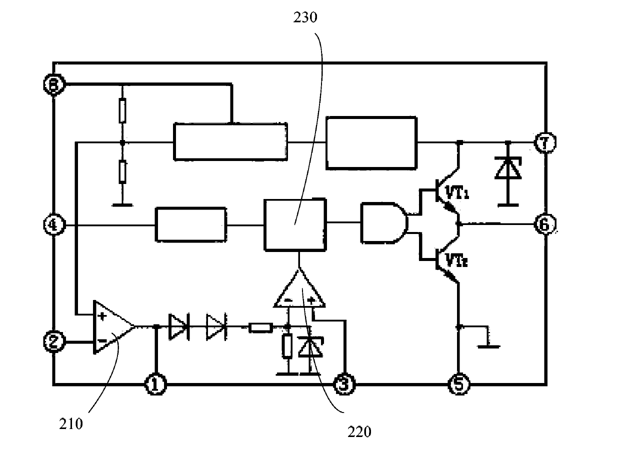
technical field [0001] The invention relates to the field of switching power supply circuits, in particular to a switching power supply overcurrent protection circuit. Background technique [0002] The application of switching power supply has become more and more extensive. In order to improve the reliability of switching power supply, a reasonable protection circuit must be designed. Overcurrent protection is one of the protection circuits, used to protect the power supply and power switching devices when the output is overloaded or short-circuited. There are usually two methods of overcurrent protection for switching power supplies, pulse width modulation and frequency modulation. The pulse width modulation (PWM) method keeps the pulse frequency constant and controls the output voltage by changing the pulse width. It is the most commonly used modulation method for switching power supplies. [0003] figure 2 It is a block diagram of the internal principle of a pulse widt...

Claims


Application Information

Patent Timeline
IPC IPC(8): H02H7/10
Inventor 周明杰邵贤辉
Owner SHENZHEN OCEANS KING LIGHTING ENG CO LTD
Learn More