Overcurrent protection circuit, control method and device, and terminal

An overcurrent protection circuit and control method technology, applied in the electronic field, can solve problems such as burning terminals, safety risks, and user property losses, and achieve the effects of overcurrent protection, improved reliability, and reduced after-sales maintenance costs

Inactive Publication Date: 2018-01-30
NUBIA TECHNOLOGY CO LTD
View PDF3 Cites 3 Cited by
  • Summary
  • Abstract
  • Description
  • Claims
  • Application Information

AI Technical Summary

Problems solved by technology

[0003] However, just because of the pluggable characteristics of this type of connector, when the terminal using this type of connector is connected to an OTG (On-The-Go) device, in the case of damage to the OTG device, or when the OTG device is inserted into the terminal If this type of connector is not completely aligned, the +5VPIN pin of this type of connector may be short-circuited to the ground. In this case, a large current will be generated, which is very likely to burn the terminal and bring property to the user. Loss and Safety Risk

Method used


Image

  • Overcurrent protection circuit, control method and device, and terminal
  • Overcurrent protection circuit, control method and device, and terminal
  • Overcurrent protection circuit, control method and device, and terminal

Examples


no. 1 example

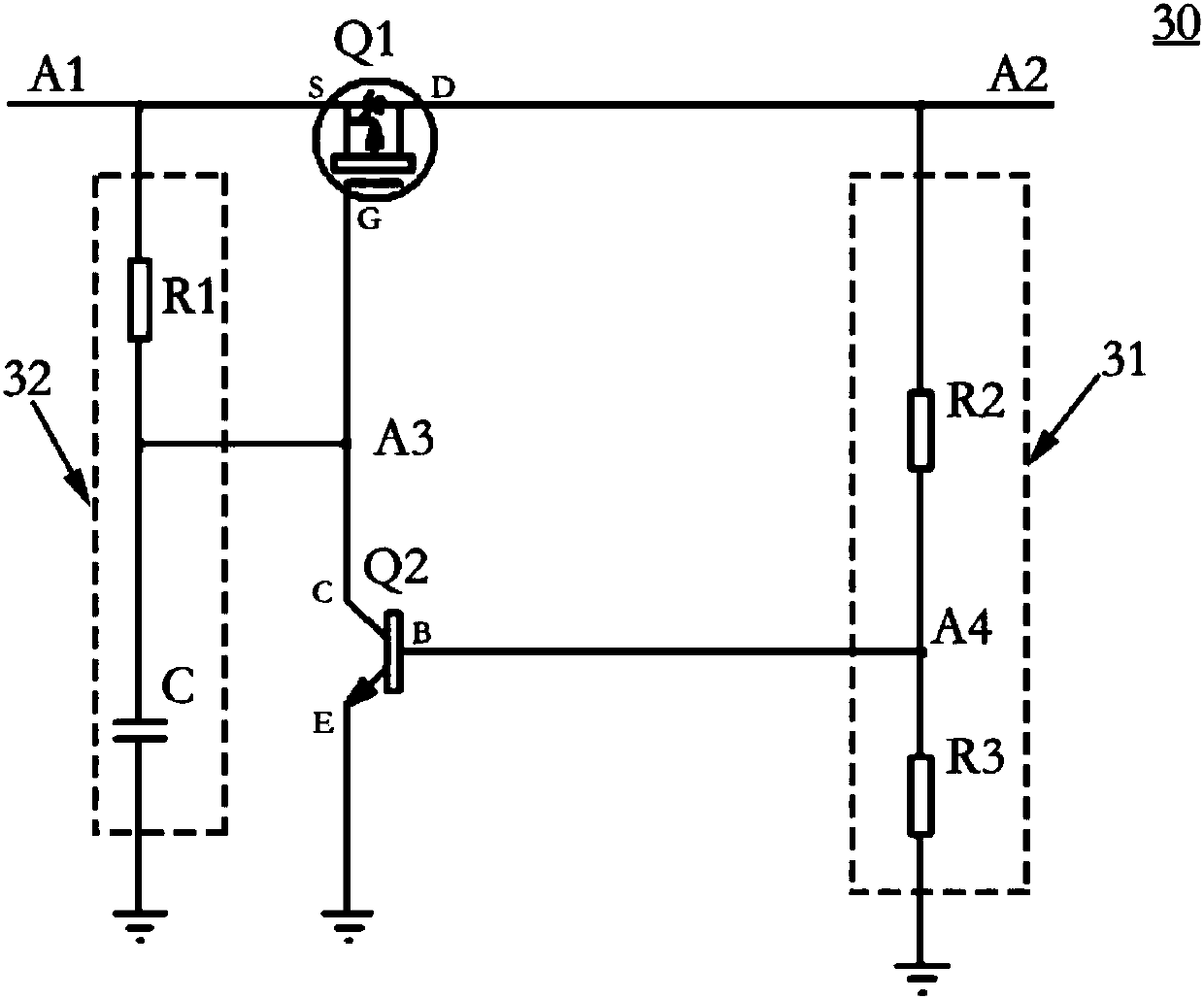
[0064] Such as image 3 as shown, image 3 An overcurrent protection circuit provided in the first embodiment of the present invention, the overcurrent protection circuit 30 includes a power switch tube and a voltage divider circuit 31;

[0065] The power switch tube includes a first power switch tube Q1 and a second power switch tube Q2;

[0066] The first end of the first power switch tube Q1 is connected to the third end of the second power switch tube Q2, and the second end of the first power switch tube Q1 is connected to the output end of the terminal power supply (represented by A1 in the figure shown) connection, the third end of the first power switch tube Q1 is connected to the power supply pin (shown in A2 in the figure) that the terminal supplies power to the OTG device;

[0067]The first end of the voltage dividing circuit 31 is connected to the power supply pin of the OTG device, and the second end of the voltage dividing circuit 31 is connected to the ground; ...

no. 2 example

[0087] The second embodiment of the present invention provides a terminal, and the terminal includes the overcurrent protection circuit described in the first embodiment. For the overcurrent protection circuit, reference may be made to the above content, and details are not repeated here.

[0088] The following combination figure 1 Explain the working process of the overcurrent protection circuit in the terminal:

[0089] When point A1 gradually rises from 0V to 5V, capacitor C is charged through resistor R1, the voltage at point A3 rises from 0V, and the voltage at point A1 rises faster than point A3, so the first power switch tube Q1 starts to conduct, thus The voltage at point A4 also starts to rise. When the voltage at point A4 reaches above 0.7V, the second power switch tube Q2 is turned on, causing the voltage at point A3 to drop, the first power switch tube Q1 is completely turned on, and the voltage at point A2 is equal to point A1. The terminal starts to supply powe...

no. 3 example

[0093] Based on the overcurrent protection circuit of the first embodiment, please refer to Figure 4 , Figure 4 A method for controlling an overcurrent protection circuit provided in the third embodiment of the present invention, the method includes the steps of:

[0094] S41. Acquire the voltage value of the voltage divider circuit.

[0095] S42. If the voltage value of the voltage dividing circuit is lower than the preset voltage value, control the first power switch tube and the second power switch tube to be cut off, so that the terminal power supply output end is disconnected from the OTG device.

[0096] In one embodiment, the method also includes the steps of:

[0097] If the voltage value of the voltage divider circuit is higher than the preset voltage value, then control the first power switch tube and the second power switch tube to be turned on, so that the terminal power output terminal is established with the OTG device connect.

[0098] As an example, the f...


PUM


Abstract

The invention discloses an overcurrent protection circuit, a control method, a control device, and a terminal. The overcurrent protection circuit comprises a power switching tube and a voltage dividing circuit, wherein the power switching tube comprises a first power switching tube and a second power switching tube; a first end of the first power switching tube is connected with a third end of thesecond power switching tube, a second end of the first power switching tube is connected with an output end of a terminal power supply, and a third end of the first power switching tube is connectedwith a power supply pin, which is for supplying power to OTG equipment, of a terminal; a first end of the voltage dividing circuit is connected with the power supply pin for supplying power to the OTGequipment, and a second end of the voltage dividing circuit is connected to the ground; a third end of the voltage dividing circuit is connected with a first end of the second power switching tube; and a second end of the second power switching tube is connected to the ground. The overcurrent protection circuit, the control method, the control device and the terminal can effectively solve the problems of short circuit and overcurrent caused by the situation that the OTG equipment is inserted improperly, realize overcurrent protection, improve the reliability and stability of terminal products, and reduce the after-sale maintenance cost.

Description

technical field [0001] The invention relates to the field of electronic technology, in particular to an overcurrent protection circuit, a control method and device, and a terminal. Background technique [0002] At present, connectors that support USB (Universal Serial Bus, Universal Serial Bus) interface double-sided insertion, such as Type-C connectors, such connectors have the function of "positive and negative insertion" that can be inserted from both sides. , bringing great convenience to users. Therefore, on more and more terminals such as mobile phones, tablet computers or other portable portable products, such connectors with "positive and negative plug-in" functions have begun to be used to realize functions such as adapter charging interfaces and data transmission ports. [0003] However, just because of the pluggable characteristics of this type of connector, when the terminal using this type of connector is connected to an OTG (On-The-Go) device, in the case of d...

Claims


Application Information

Patent Timeline
Patent Type & Authority Applications(China)
IPC IPC(8): H02H3/08H04B1/40
Inventor 刘娇
Owner NUBIA TECHNOLOGY CO LTD
Why Eureka
Try Eureka