
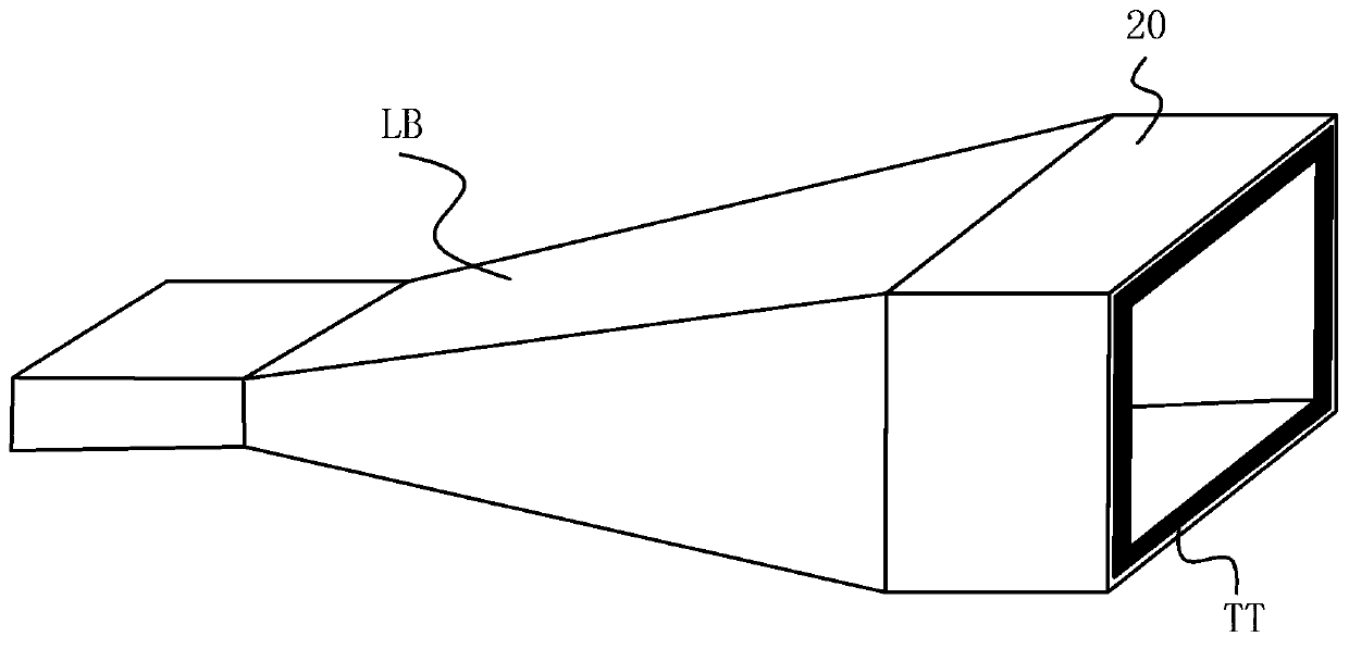
a horn antenna

A horn antenna and horn technology, applied in the field of communication, can solve the problems of high cost and difficult processing of the horn antenna, and achieve the effects of uniform amplitude distribution, improved utilization efficiency, and improved far-field gain

Active Publication Date: 2018-04-17
KUANG CHI INST OF ADVANCED TECH
View PDF3 Cites 0 Cited by
  • Summary
  • Abstract
  • Description
  • Claims
  • Application Information

AI Technical Summary

Problems solved by technology

[0003] The technical problem to be solved by the present invention is to provide a horn antenna with a simple structure in view of the defects of the existing horn antennas, which are difficult to process and high in cost.

Method used


Image

  • a horn antenna
  • a horn antenna
  • a horn antenna

Examples


no. 1 example

[0042] According to the first embodiment, a simulation test is carried out on a horn antenna with the following parameters:

[0043] The center frequency of the horn antenna is 18.356GHZ;

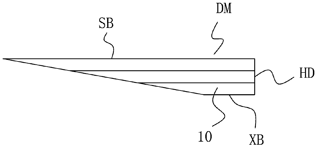
[0044] Such as image 3 As shown, the upper side SB of the right-angled trapezoidal section of the metamaterial sleeve TT is 19 mm, the lower side XB is 3 mm, and the height (that is, the radial thickness HD of the metamaterial sleeve) is 3.054 mm.

[0045] The refractive index of the section of the metamaterial sleeve TT close to the horn aperture surface is 1.56. Along the direction perpendicular to the horn aperture surface from inside to outside, the refractive index of each section increases gradually, and the outermost section has a refractive index of 8.

[0046] Such as Figure 8 Shown is the far-field diagram of the horn antenna, from Figure 8 It can be seen from the figure that the gain of the horn antenna of this embodiment is improved compared with the standard horn.

[004...


PUM


Abstract

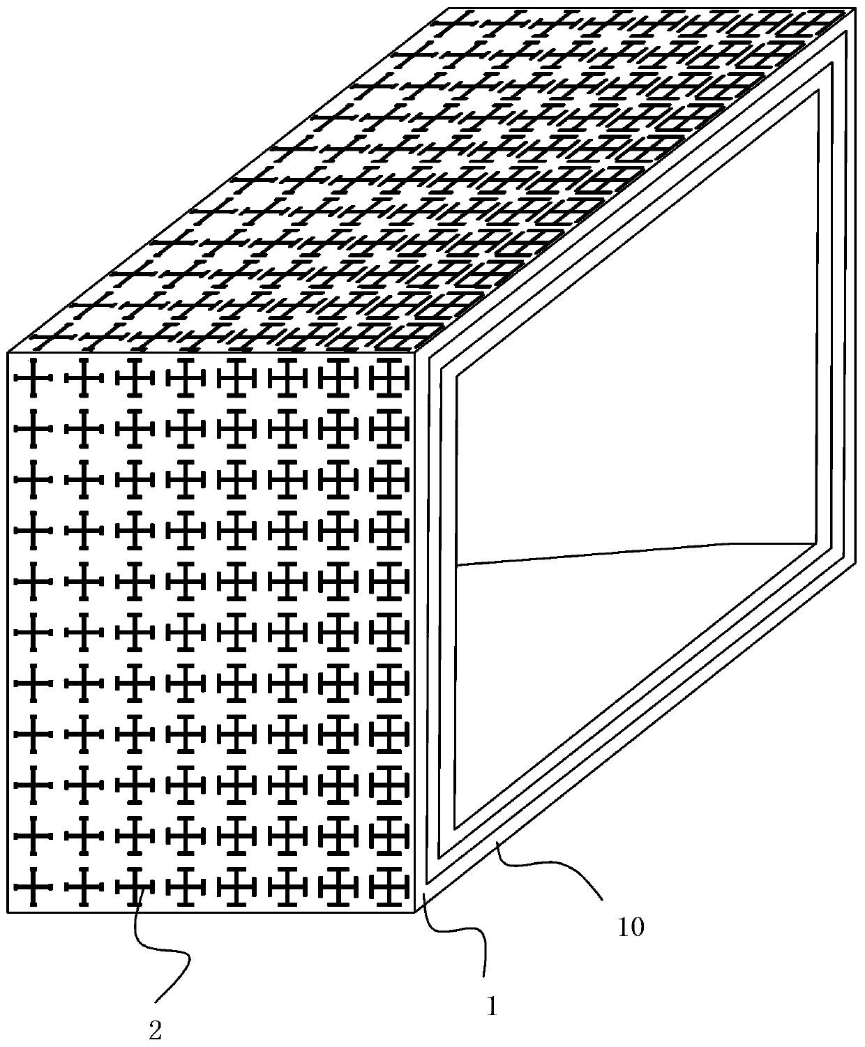
The invention relates to a horn antenna, comprising a horn and a metamaterial sleeve arranged at the opening of the horn, the metamaterial sleeve includes at least one metamaterial ring layer, and the metamaterial ring layer includes a ring substrate and a ring attached to the ring. There are multiple artificial microstructures on the outer surface of the shaped substrate, and the refractive index of any section of each metamaterial ring layer gradually increases from inside to outside along the direction perpendicular to the horn aperture surface. According to the horn antenna of the present invention, adding a metamaterial sleeve with a gradually changing refractive index to the opening of the standard horn can make the amplitude distribution of the wavefront electric field more uniform, thereby improving the utilization efficiency of the horn antenna aperture surface and improving the horn antenna. far-field gain.

Description

technical field [0001] The present invention relates to the communication field, and more specifically, relates to a horn antenna. Background technique [0002] Horn antenna, that is, the antenna whose waveguide terminal is opened into a horn shape, due to the simple structure of the horn antenna and the easy control of the pattern, it is usually used as a medium directional antenna, such as a standard horn, and is most commonly used as a feed source for the reflector; the horn antenna has The advantages of simple structure, low cost, high gain, etc. are widely used in engineering, but in some special fields, due to the limitations of working environment and equipped equipment, it is often required to further improve the gain performance. The traditional method is to add phase correction Reflective surface or lens, but these structures are curved surface structures, which are inconvenient in processing and installation. Contents of the invention [0003] The technical pro...

Claims


Application Information

Patent Timeline
Patent Type & Authority Patents(China)
IPC IPC(8): H01Q19/08H01Q15/02
Inventor 刘若鹏季春霖岳玉涛郭洁刘豫青
Owner KUANG CHI INST OF ADVANCED TECH
Learn More