
A Miniaturized High Gain Metamaterial Horn Antenna

A horn antenna and metamaterial technology, applied in the direction of waveguide horn, radiation element structure, circuit, etc., can solve the problems of long design cycle, large volume, complex processing, etc., achieve low cost, simple assembly, and improve far-field gain Effect

Active Publication Date: 2019-06-14
SHANGHAI INST OF MICROSYSTEM & INFORMATION TECH CHINESE ACAD OF SCI
View PDF6 Cites 0 Cited by
  • Summary
  • Abstract
  • Description
  • Claims
  • Application Information

AI Technical Summary

Problems solved by technology

However, this design needs to use a 6-layer structure, which is large in size, complex in processing, and long in design cycle

Method used


Image

  • A Miniaturized High Gain Metamaterial Horn Antenna
  • A Miniaturized High Gain Metamaterial Horn Antenna
  • A Miniaturized High Gain Metamaterial Horn Antenna

Examples


Embodiment Construction

[0025] Below in conjunction with specific embodiment, further illustrate the present invention. It should be understood that these examples are only used to illustrate the present invention and are not intended to limit the scope of the present invention. In addition, it should be understood that after reading the teachings of the present invention, those skilled in the art can make various changes or modifications to the present invention, and these equivalent forms also fall within the scope defined by the appended claims of the present application.

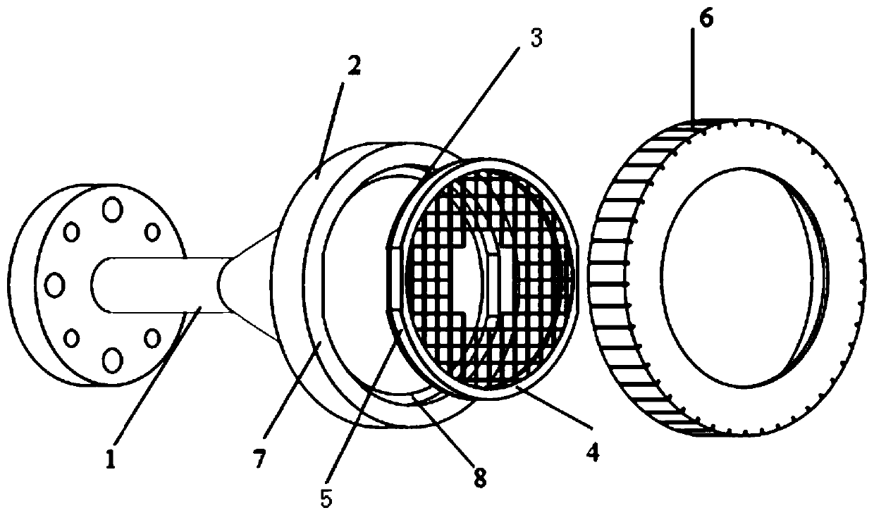
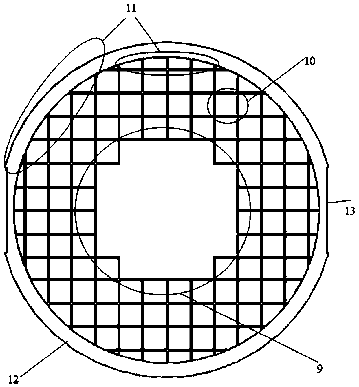
[0026] Such as figure 1 As shown, the miniaturized high-gain metamaterial horn antenna of the present invention includes a horn antenna body 1 (here exemplarily shown as a conical horn antenna body), and the horn antenna body 1 is provided with a A step hole 8 is fixed in the step hole 8 to make a phase distribution adjustment module for uniformizing the electromagnetic wave phase distribution of the output port surface 7, and...


PUM


Abstract

The invention provides a miniaturized high-gain metamaterial horn antenna. The miniaturized high-gain metamaterial horn antenna comprises a horn antenna body, the horn antenna body is provided with a step hole which extends inwards from an output port surface, the interior of the step hole is fixedly provided with a phase distribution regulation module which is used for making electromagnetic waves in the output port surface in uniform phase distribution; the phase distribution regulation module comprises at least two inhomogeneous metamaterial metal sheets which are arranged in an overlapping mode, a metallic gasket is arranged between two adjacent inhomogeneous metamaterial metal sheets, and the outer side surface of each outermost inhomogeneous metamaterial metal sheet is flush with the output port surface. According to the miniaturized high-gain metamaterial horn antenna, miniaturization, light weight and integration of the horn antenna can be guaranteed on the premise that high far-field benefit is achieved.

Description

technical field [0001] The invention relates to the technical field of millimeter wave antennas, in particular to a miniaturized high-gain metamaterial horn antenna. Background technique [0002] Antennas are indispensable devices in modern communication systems and radar systems. Among them, the horn antenna is the most common form, because of its simple design, high power capacity, and low return loss, it is especially suitable for high-frequency and high-power systems. However, with the rapid development of modern communication technology and radar systems, higher requirements are placed on the performance of horn antennas. For example, the size of the horn antenna is required to be reduced while its far-field gain remains unchanged, that is, the horn antenna is required to be more miniaturized, lightweight, and integrated. At the same time, higher requirements are put forward for the cost control of the horn antenna. With the in-depth study of metamaterials in the sci...

Claims


Application Information

Patent Timeline
Patent Type & Authority Patents(China)
IPC IPC(8): H01Q13/02H01Q1/36
CPCH01Q1/36H01Q13/02
Inventor 李凌云黄彬孙浩孙芸佟瑞
Owner SHANGHAI INST OF MICROSYSTEM & INFORMATION TECH CHINESE ACAD OF SCI
Learn More