
Miniaturized h-plane horn antenna, radar and communication system loaded with slow wave structure

A technology of slow-wave structure and horn antenna, which is applied in the field of radar, communication system, and H-plane horn antenna. It can solve the problems that the energy stored in the near-field area is not easy to radiate, the mouth-face phase cannot be adjusted, and the antenna gain becomes worse. , to achieve the effect of convenient design, simple power feeding and small overall size

Active Publication Date: 2021-09-28
XIDIAN UNIV
View PDF6 Cites 0 Cited by
  • Summary
  • Abstract
  • Description
  • Claims
  • Application Information

AI Technical Summary

Problems solved by technology

However, if a periodic structure of the same height is directly etched on the inner surface of the horn, it is easy to store energy in the near-field area, which is not easy to radiate, and the bandwidth is narrowed or the mouth-face phase cannot be adjusted, resulting in poor antenna gain.

Method used


Image

  • Miniaturized h-plane horn antenna, radar and communication system loaded with slow wave structure
  • Miniaturized h-plane horn antenna, radar and communication system loaded with slow wave structure
  • Miniaturized h-plane horn antenna, radar and communication system loaded with slow wave structure

Examples


Embodiment Construction

[0026] In order to make the object, technical solution and advantages of the present invention more clear, the present invention will be further described in detail below in conjunction with the examples. It should be understood that the specific embodiments described here are only used to explain the present invention, not to limit the present invention.

[0027] Aiming at the problems existing in the prior art, the present invention provides a miniaturized H-plane horn antenna, radar, and communication system loaded with a slow wave structure. The present invention will be described in detail below in conjunction with the accompanying drawings.

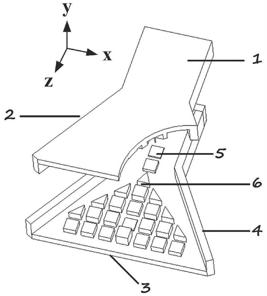
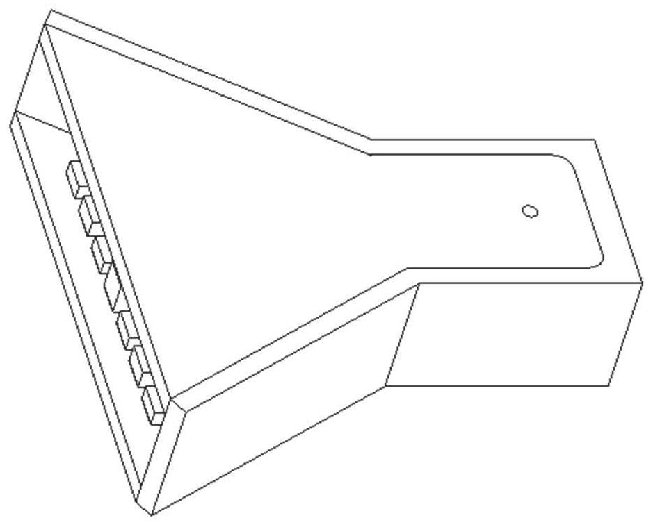
[0028] Such as figure 1 and figure 2 As shown, the miniaturized H-plane horn antenna loaded with slow wave structure provided by the embodiment of the present invention includes: feed waveguide 1, oblate cone horn structure 2, horn wide metal wall 3, horn narrow metal wall 4, square metal Column 5, slow wave structure 6.

[0029...


PUM


Abstract

The invention belongs to the technical field of antennas, and discloses a miniaturized H-plane horn antenna, radar, and communication system loaded with a slow-wave structure, including: a waveguide, an H-plane horn structure, and a slow-wave structure; There is a row of two symmetrical square metal pillars on the surface; the slow wave structure is arranged on the upper and lower inner surfaces of the wide surface of the horn body of the H-plane, and the slow wave structure is composed of multiple rows of symmetrical metal pillars. The distance between them is equal. Compared with the conventional H-plane horn antenna with the same caliber in the working frequency band, the invention has smaller longitudinal size, wider bandwidth and higher gain, and realizes the miniaturization of the horn antenna. The invention uses the integrated slow wave structure to make the phase distribution of the electromagnetic wave on the output port surface uniform and improve the far field gain. The design has the advantages of small overall size, simple power feeding, convenient design, low cost and easy assembly, and has the advantages of miniaturization and integration .

Description

technical field [0001] The invention belongs to the technical field of antennas, and in particular relates to a miniaturized H-plane horn antenna, a radar and a communication system loaded with a slow wave structure. Background technique [0002] At present, the closest existing technology: In modern communication systems and radar systems, antennas are indispensable devices. Among them, the horn antenna is one of the most widely used antennas, and its advantages are simple structure, convenient manufacture, convenient feeding and large power capacity. With the continuous development of millimeter-wave devices and systems, people pay special attention to the miniaturization of devices and systems. As an important part of radio receiving and transmitting systems, antennas are of great significance to improve their performance and reduce their size. For example, horn antennas are required to be reduced in size without changing their far-field gain. However, the reduction of ...

Claims


Application Information

Patent Timeline
Patent Type & Authority Patents(China)
IPC IPC(8): H01Q1/36H01Q1/38H01Q13/02
CPCH01Q1/36H01Q1/38H01Q13/02
Inventor 邓敬亚孙冬全罗瑞清雒艳雍婷郭立新张小苗
Owner XIDIAN UNIV
Learn More