
Drying drum and dryer with same

A drum and cylinder technology, applied in the field of material drying equipment, can solve the problems of hollow drying drum, concentrated material throwing position, small contact area of ​​material and heating airflow, etc., to improve thermal efficiency and increase contact heat exchange area Effect

Active Publication Date: 2014-03-26
ZOOMLION HEAVY IND CO LTD
View PDF5 Cites 2 Cited by
  • Summary
  • Abstract
  • Description
  • Claims
  • Application Information

AI Technical Summary

Problems solved by technology

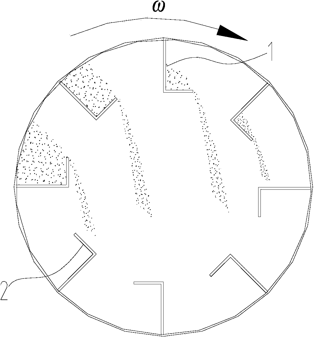
refer to figure 1 , when the material lifting plates of these two structures are lifting materials, because each panel is a rectangular structure, and under the action of material gravity, the material throwing position is concentrated, so it is difficult to form a connected material curtain, resulting in Large-area voids, small contact area between materials and heating air flow, resulting in low drying efficiency and high energy consumption, which cannot meet the requirements of energy saving and emission reduction

Method used


Image

  • Drying drum and dryer with same
  • Drying drum and dryer with same
  • Drying drum and dryer with same

Examples


Embodiment Construction

[0031] Specific embodiments of the present invention will be described in detail below in conjunction with the accompanying drawings. It should be understood that the specific embodiments described here are only used to illustrate and explain the present invention, and are not intended to limit the present invention.

[0032] In the present invention, in the case of no contrary description, the used orientation words such as "up, down, left and right" usually refer to the up, down, left and right shown in the accompanying drawings; "inside and outside" Refers to the inside and outside of the outline of each part itself.

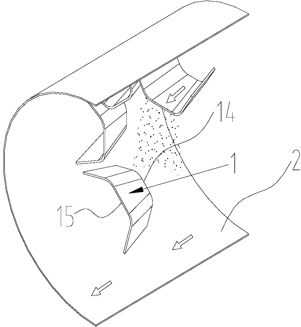
[0033] Such as Figure 3 to Figure 8 As shown, the present invention provides a drying drum, comprising a cylinder body 2, the cylinder body 2 has a feed inlet and a discharge port arranged oppositely, and a material lifting plate 1 is fixedly arranged on the inner wall surface of the cylinder body 2, wherein the lifting The feed port 14 of the material pla...


PUM


Abstract

The invention provides a drying drum. The drying drum comprises a drum body. The drum body is provided with a feed inlet and a discharge outlet which are arranged opposite to each other. The inner wall face of the drum body is fixedly provided with a material lifting plate, the feed port of the material lifting plate faces towards the feed inlet of the drum body, the discharge port of the material lifting plate faces towards the discharge outlet of the drum body, the material lifting plate is of a gradually-expanding structure in the axial direction of the drum body, and the size of the cross section of the discharge port of the material lifting plate is larger than the size of the cross section of the feed port of the material lifting plate, so that the total extending length of the discharge end of the material lifting plate is larger than that of the feed end of the material lifting plate, the spraying width of materials at the discharge end of the material lifting plate is increased, the materials sprayed out of the cross section of the drying drum form waterfall continuous materials curtains easily, the area of cavities in the cross section of the drying drum is reduced, the contact heat exchange area between the materials and hot airflow is increased, then the heat efficiency of the dryer is improved, and the purpose of energy conservation and emission reduction is achieved.

Description

technical field [0001] The invention relates to material drying equipment, in particular to a drying drum and a dryer with the same. Background technique [0002] In the production of building materials industry, the raw materials, fuels and mixtures used all contain a certain amount of moisture. Dry them to reduce the moisture content to meet the moisture requirements of materials for calculation, transportation and homogenization. It is also conducive to ensuring product quality and improving the system. normal operating rate. At present, the commonly used drying equipment is a drum rotary dryer. This dryer can be used in dry-mixed mortar drying system for drying solid materials. [0003] Existing dryers include a drying drum and related driving devices, etc., wherein the drying drum includes a cylinder and a lifting plate arranged in the cylinder. When working, the cylinder rotates under the drive of the driving device, and the cylinder in the cylinder rotates. The mat...

Claims


Application Information

Patent Timeline
Patent Type & Authority Applications(China)
IPC IPC(8): F26B25/08F26B25/16F26B11/02
Inventor 张斌万军尹友中姜方宁张劲
Owner ZOOMLION HEAVY IND CO LTD
Learn More