Metal Fuel Cell System

A metal fuel cell and electric stack technology, applied in fuel cells, fuel cell additives, fuel cell heat exchange, etc., can solve the problems of single heat dissipation method and poor heat dissipation effect

Active Publication Date: 2021-06-04
郑州佛光发电设备股份有限公司
View PDF7 Cites 0 Cited by
  • Summary
  • Abstract
  • Description
  • Claims
  • Application Information

AI Technical Summary

Problems solved by technology

[0006] In order to solve the problems of single heat dissipation mode and poor heat dissipation effect of existing metal fuel cells, the present invention innovatively provides a metal fuel cell system, which combines heat pipe and liquid cooling heat dissipation methods, and can Quickly adjust the electrolyte temperature within a short time, improve the heat dissipation and cooling efficiency, and maintain the reaction temperature of the metal fuel cell system within a suitable temperature range, so that the chemical reaction can proceed smoothly and improve the power generation efficiency

Method used


Image

  • Metal Fuel Cell System
  • Metal Fuel Cell System
  • Metal Fuel Cell System

Examples


Embodiment Construction

[0032] The metal fuel cell system provided by the present invention will be explained and described in detail below in conjunction with the accompanying drawings.

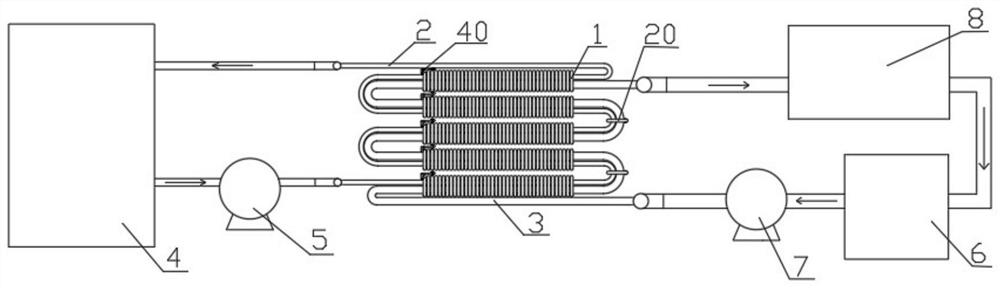
[0033] figure 1 Schematic diagram of the metal fuel cell system. Such as figure 1 As shown, this embodiment specifically discloses a metal fuel cell system, including: a coolant tank 4 , an electrolyte tank 6 , an electric stack 8 , a coolant pipe 2 , an electrolyte pipe 3 and a plurality of heat pipes 1 .

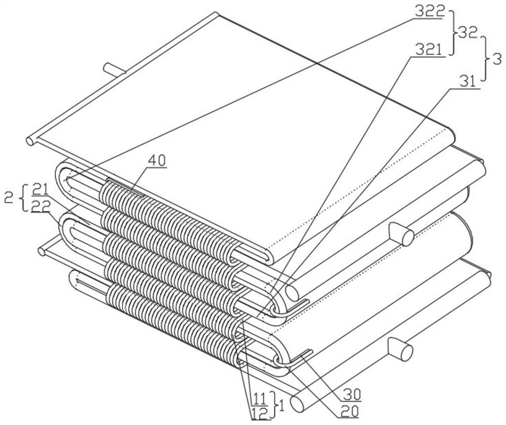
[0034] Such as figure 1 and 2 As shown, the cooling liquid pipe 2 and the electrolyte pipe 3 are both multi-layer S-shaped pipes, and both the cooling liquid pipe 2 and the electrolyte pipe 3 include a horizontal part and a curved part connecting the upper and lower horizontal parts, and the horizontal part of the cooling liquid pipe The portion 21 overlaps with the horizontal portion 31 of the electrolyte pipe, and the curved portion 22 of the cooling liquid pipe abuts against the curved portion 32 of the ...


PUM


Abstract

The invention discloses a metal fuel cell system, comprising: a cooling liquid tank, an electrolyte tank, an electric stack, a cooling liquid pipe, an electrolyte pipe and a plurality of heat pipes, and the cooling liquid pipe and the electrolyte pipe are both multi-layer S-shaped pipes , a plurality of heat pipes are clamped on the horizontal part of the cooling liquid pipe and the horizontal part of the electrolyte pipe stacked on each layer, the liquid inlet of the cooling liquid pipe is connected with the liquid supply port of the cooling liquid tank, and the liquid outlet of the cooling liquid pipe It is connected to the liquid return port of the coolant tank, and the first circulation pump is connected between the coolant pipe and the coolant tank; the liquid inlet of the electrolyte pipe is connected to the liquid supply port of the electrolyte tank through the second circulation pump, and the electrolyte The liquid outlet of the tube is connected with the liquid inlet of the stack, and the liquid outlet of the stack is connected with the liquid return port of the electrolyte tank. The metal fuel cell system of the present invention adopts a heat dissipation method combining heat pipes and liquid cooling, which can quickly adjust the electrolyte temperature in a short time, significantly improve the heat dissipation and cooling efficiency, and improve the power generation efficiency of the metal fuel cell system.

Description

technical field [0001] The invention relates to the field of metal fuel cells, and more specifically, the invention relates to a metal fuel cell system. Background technique [0002] Metal fuel cell, as the name implies, is a new type of battery that uses metal and air as battery materials. It is a non-polluting, long-lasting, stable and reliable power source, and a battery that is very friendly to the environment. Metal fuel cells have great adaptability. They can be used not only as power batteries, but also as signal batteries with long life and high specific energy. It is a very powerful battery with broad application prospects. [0003] Metal fuel cells use the chemical reaction between the metal anode and the air cathode to generate electricity. The reaction will release a lot of heat. The heat generated by the reaction needs to be taken away in time to ensure that the chemical reaction is within a suitable temperature range and improve the power generation efficiency...

Claims


Application Information

Patent Timeline
Patent Type & Authority Patents(China)
IPC IPC(8): H01M8/04007H01M8/04029H01M8/04276
CPCH01M8/04029H01M8/04067H01M8/04276Y02E60/50
Inventor 张钧张艳娜吴磊吕涛
Owner 郑州佛光发电设备股份有限公司
Why Eureka
Try Eureka