Turbocharger

A turbocharger, turbine technology, applied in the direction of machine/engine, bearing, shaft and bearing, etc., can solve the problems of low rotor speed, short bearing life, oil leakage, etc., to achieve outstanding high temperature resistance, high product speed, The effect of long product life

Active Publication Date: 2014-03-26
HUNAN UNIV
View PDF3 Cites 24 Cited by
  • Summary
  • Abstract
  • Description
  • Claims
  • Application Information

AI Technical Summary

Problems solved by technology

[0004] At present, the bearings of turbochargers usually use rolling bearings and sliding bearings, which have the following problems: due to the use of lubricating oil, oil leakage is inevitable, resulting in oil leakage through the oil seal and contamination of the working surface of the intercooler The problem of low rotor speed due to friction, low efficiency; and short bearing life due to wear

Method used


Image

  • Turbocharger
  • Turbocharger
  • Turbocharger

Examples


Embodiment Construction

[0024] The present invention will be further described in detail below in conjunction with the accompanying drawings and specific embodiments.

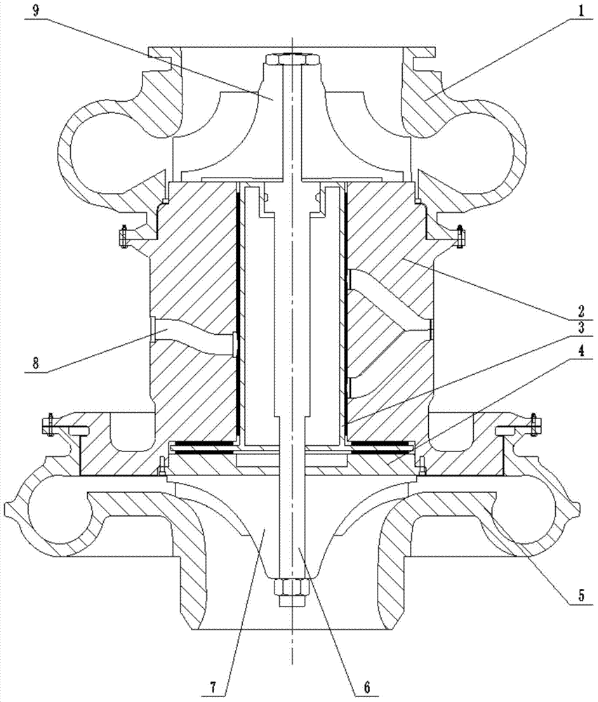
[0025] figure 1 It is a schematic diagram of the overall structure of a turbocharger using air bearings. The turbocharger of the present invention includes a turbine casing 5 , a turbine 7 , a rotor shaft 6 , a main body 2 , a thrust bearing cover 4 , a radial-thrust bearing 3 , an impeller casing 1 , and an impeller 9 .

[0026] Among them, the impeller 9, the radial-thrust bearing 3, the thrust bearing cover 4 and the turbine 7 are sequentially set on the rotor shaft 6, the radial-thrust bearing 3 and the rotor shaft 6 are interference fit, the thrust bearing cover 4 and the diameter Fastened to the thrust bearing 3, the impeller 9 and the turbine 7 are respectively fastened to the two ends of the rotor shaft 6, and the impeller shell 1 and the turbine shell 5 are respectively fastened to the two ends of the main body 2. The above-...


PUM


Abstract

The invention relates to a turbocharger which comprises a turbine shell (5), a turbine (7), a rotor shaft (6), a body (2), a thrusting bearing cover (4), a radial thrusting bearing (3), an impeller shell (1) and an impeller (9). The radial thrusting bearing (3) comprises a radial metal rubber block type air bearing, a radial thrusting bearing rotor shaft and a thrusting metal rubber block type air bearing and the radial metal rubber block type air bearing and the thrusting metal rubber block type air bearing respectively comprise a bearing metal rubber block, a bearing elastic foil sheet and a bearing top-layer foil sheet. The turbocharger has the advantages of being suitable for energy recovery of engine tail gas and air inlet supercharge of an engine, capable of avoiding the influence, caused by oil leakage of the turbocharger, on correct timing of the engine through the air bearings, suitable for large-discharge engines due to the small air lubrication resistance and high product rotation speed, long in service life due to the fact that direct physical contact between the surface of the rotor shaft and the inner surface of the bearing is avoided, and remarkable in high-temperature-resistant performance due to the fact that a bearing medium of the bearing is air.

Description

technical field [0001] The invention relates to a turbocharger, which mainly aims at improving the structure and design of the existing turbocharger bearing. Background technique [0002] As one of the main forms of convenient power at present, fuel engine technology is an important pillar industry for the development of the national economy. It is widely used in industrial and agricultural production, transportation, and standby power generation. The heat energy generated by fuel in the engine combustion chamber is only 25 % to 40% is converted into useful mechanical energy, and most of the rest is wasted in the form of heat and kinetic energy of combustion exhaust gas. It can be seen that the utilization of engine exhaust gas is an important way for the engine to improve power efficiency. [0003] The exhaust gas discharged from the fuel engine has the characteristics of high temperature, high speed, and high pressure, which can drive the turbine to rotate and further driv...

Claims


Application Information

Patent Timeline
Patent Type & Authority Applications(China)
IPC IPC(8): F02B37/00F16C32/06
CPCY02T10/12
Inventor 冯凯郭志阳赵雪源刘玉满
Owner HUNAN UNIV
Why Eureka
Try Eureka