
Internally heated coal carbonization furnace, internally heated coal carbonization system and coal carbonization technical method

A coal dry distillation and internal heating technology, which is applied in special forms of dry distillation, direct heating dry distillation, coking oven with vertical carbonization chamber, etc., can solve the problem of reducing the yield of semi-coke products, reducing the combustion and thermal efficiency of the combustion chamber, and limiting the coking process and efficiency, to simplify the mechanical structure and working principle, reduce design and construction costs, and improve effective space utilization

Active Publication Date: 2014-03-26
陈晓辉
View PDF8 Cites 13 Cited by
  • Summary
  • Abstract
  • Description
  • Claims
  • Application Information

AI Technical Summary

Problems solved by technology

[0017] 1) The wall of the carbonization chamber is generally made of 100 mm thick silica bricks under the condition of comprehensive consideration and balance of strength and thermal conductivity, whose thermal conductivity and efficiency seriously affect and limit the coking process and efficiency;
[0018] 2) The combustion of gas formed in the vertical flue of the combustion chamber is a typical regenerative combustion, which is characterized by low combustion efficiency and uneven temperature distribution, thus further reducing the energy efficiency of modern coking processes;
[0019] 3) The coking temperature in the carbonization chamber is generally 950°C-1050°C, and the average temperature of the vertical flue in the combustion chamber is 1300°C or higher; moreover, due to the formation of gas and air, the local high-temperature large flame is peroxygenated, resulting in A large amount of nitrogen oxides and sulfur oxides, causing serious air pollution and emissions;
[0020] 4) The carbonization chamber of the coal carbonization furnace needs to be built with a large number of silica bricks with high temperature resistance and relatively good thermal conductivity, so the construction cost of the coal carbonization furnace is high;
Because they all use conventional solid or gas fuel combustion technology, it is necessary to use excessive blowing to make the fuel burn as much as possible, resulting in too much oxygen in the generated high-temperature flue gas; it will burn and oxidize with part of the coal in the carbonization chamber, so Consuming coal and reducing the yield of semi-coke products;
[0028] 2) Conventional solid or gas fuel combustion technologies have obvious problems of low combustion efficiency and pollution emissions caused by insufficient combustion; therefore, it is usually necessary to use excessive blowing combustion methods
However, this combustion method reduces the combustion and thermal efficiency of the combustion chamber, as well as the overall energy efficiency of this internal heat carbonization process;
[0029] 3) Although the coking temperature in the carbonization chamber is about 700°C; but there must be local high temperature in the combustion chamber due to the combustion method
This combustion will produce a large amount of nitrogen oxides and sulfur oxides, causing serious air pollution and emissions

Method used


Image

  • Internally heated coal carbonization furnace, internally heated coal carbonization system and coal carbonization technical method
  • Internally heated coal carbonization furnace, internally heated coal carbonization system and coal carbonization technical method
  • Internally heated coal carbonization furnace, internally heated coal carbonization system and coal carbonization technical method

Examples


Embodiment Construction

[0069] The present invention will be described in further detail below in conjunction with the accompanying drawings.

[0070] The invention includes two parts: the structure design and the technology of the internal heating type coal carbonization furnace.

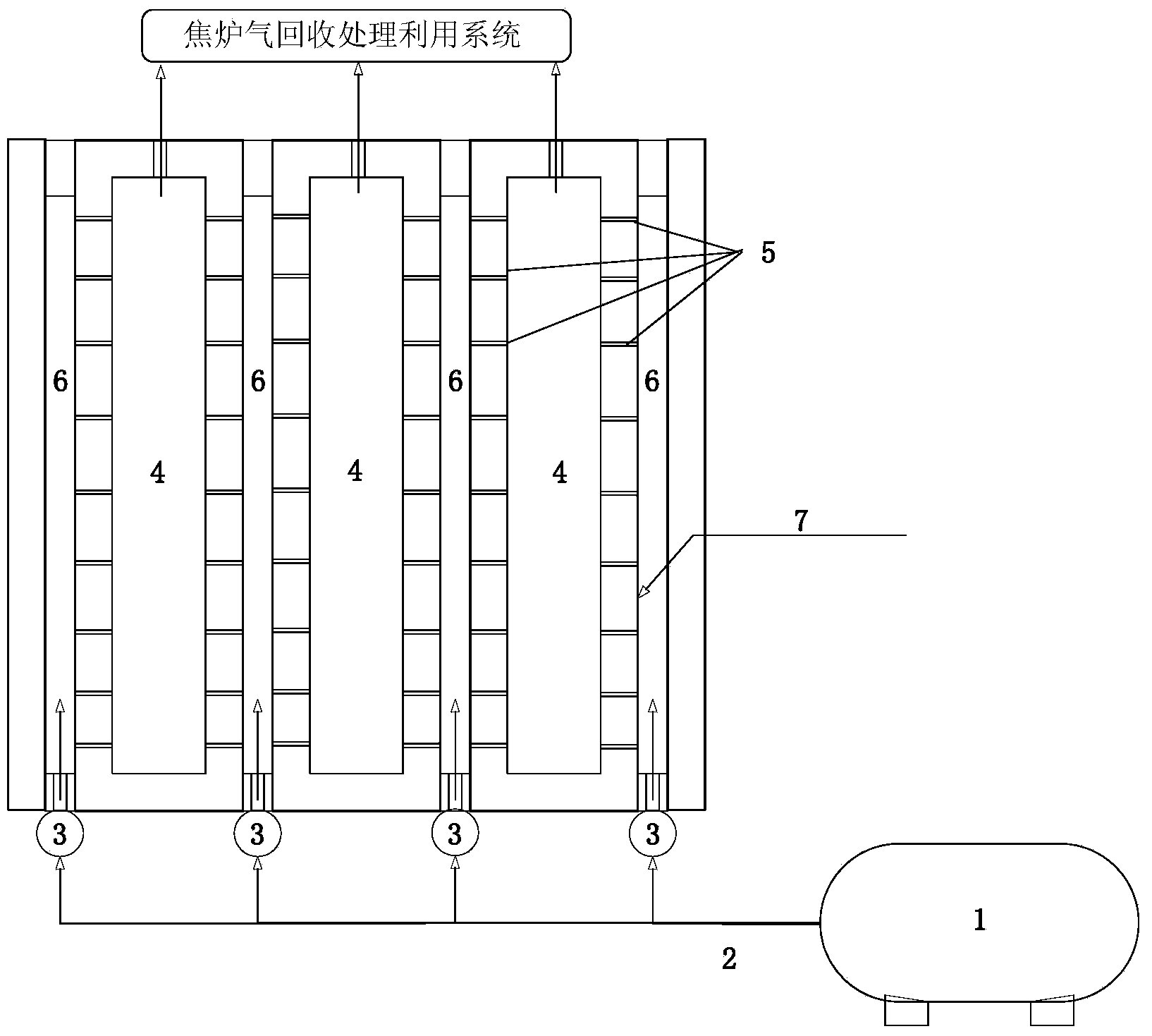
[0071] Internal heating type coal carbonization furnace of the present invention, its structure is as follows figure 1 Shown (internal heating type coal carbonization furnace described in the present invention, has canceled coal gas and air transmission and distribution system and relevant auxiliary system. figure 1 The other units, structure, equipment, process technology and flow of the coal carbonization furnace not shown in the above can be the same as the modern coal carbonization furnace, and are implemented by using the existing technology, and will not be described in detail. ),include:

[0072] Furnace body, the furnace body is provided with several carbonization chambers 4 side by side, the carbonization cham...


PUM


Abstract

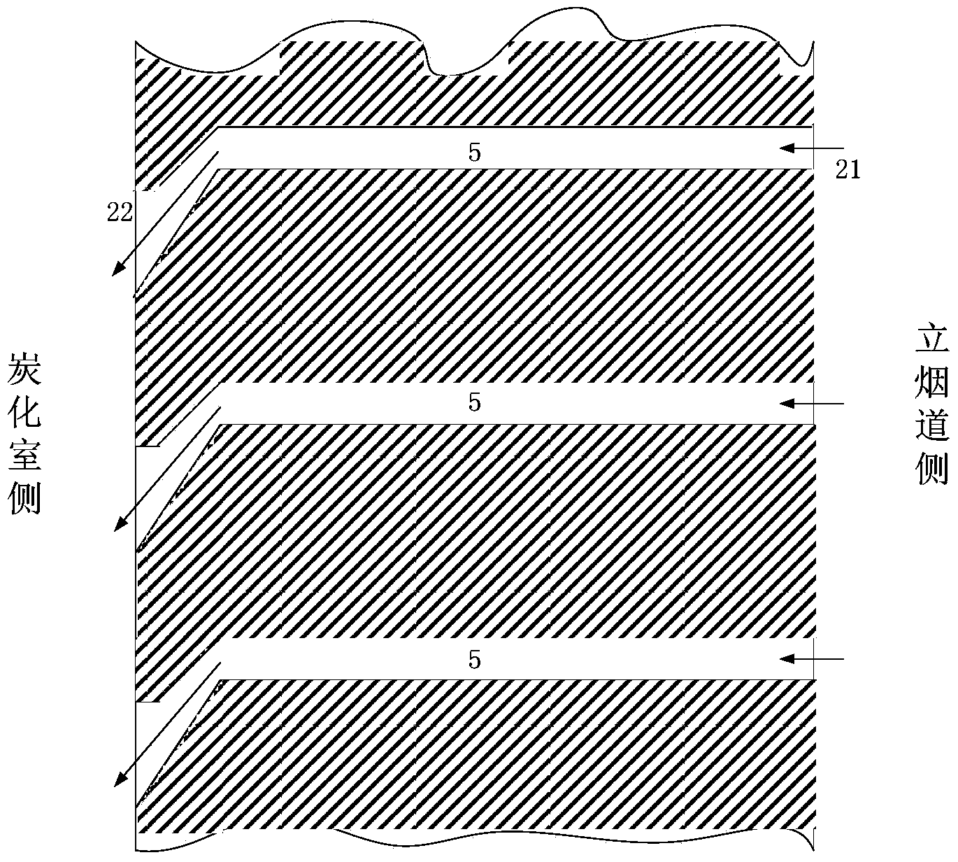
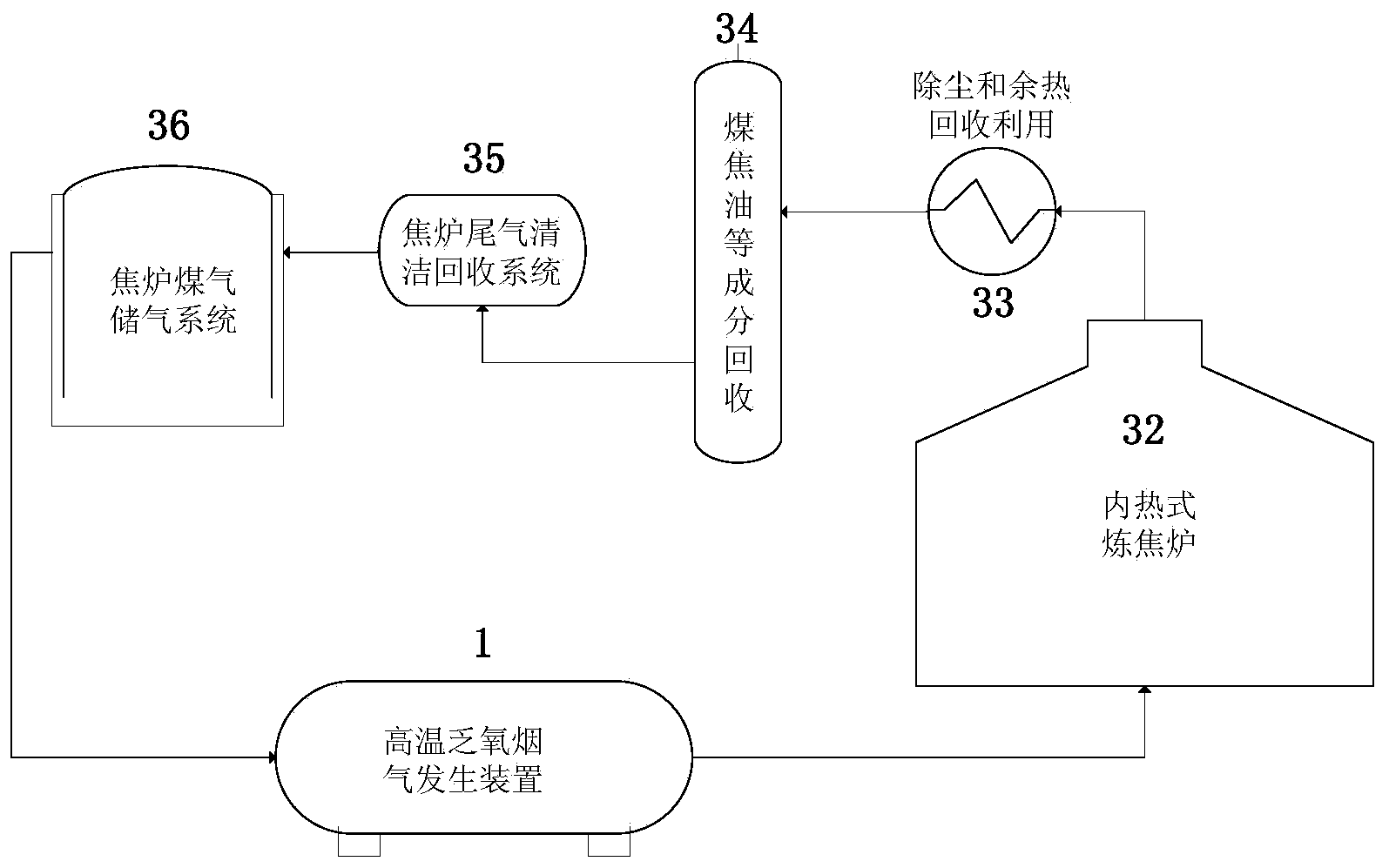
The invention relates to coal carbonization equipment and technology, and particularly relates to an internally heated coal carbonization furnace, an internally heated coal carbonization system and a coal carbonization technical method. The internally heated coal carbonization furnace comprises a furnace body, wherein a plurality of carbonization chambers are arranged in the furnace body side by side; high-temperature oxygen deficiency flue gas produced from a high-temperature oxygen deficiency flue gas generating device is directly fed to all the carbonization chambers through a vertical flue, so that the coal in the carbonization chambers is in direct contact with the high-temperature oxygen deficiency flue gas to perform coal carbonization. Walls on left and right sides of the carbonization chambers are flue gas permeability walls, and flue gas holes are formed in the wall bodies, so that the high-temperature oxygen deficiency flue gas can freely enter the carbonization chambers from the vertical flue. The internally heated coal carbonization furnace, the internally heated coal carbonization system and the coal carbonization technical method have the advantages that the efficiency is high, the energy consumption is low, the contamination factor is small, the maximization of coal carbonization efficiency is realized, the energy consumption is reduced, and the coking time is shortened.

Description

technical field [0001] The invention relates to coal dry distillation equipment and technology, in particular to an internal heat type coal dry distillation furnace, an internal heat type coal dry distillation system and a coal dry distillation process. Coal carbonization furnace is also called coking oven or carbonization furnace. Background technique [0002] Coal dry distillation (that is, coal coking) refers to the process in which coal (coal) is heated in the absence of air to produce pyrolysis to generate gas, tar, crude benzene and coke. The large-scale use of coal coking technology in industrial production began in the 18th century to produce coke needed for ironmaking. [0003] In view of the combustion characteristics of coal itself, coal coking needs to be completed under the condition of being isolated from the air, so as to avoid the direct contact between the oxygen in the air and the hot coal during the coking process to cause combustion or oxidation reaction...

Claims


Application Information

Patent Timeline
IPC IPC(8): C10B53/04C10B57/00
CPCC10B3/00C10B49/02C10B53/04
Inventor 陈晓辉
Owner 陈晓辉
Learn More