
Half stamp forging forming die

A forming die and punching forging technology, applied in the field of punching and forging forming die, can solve the problems of high cost, low efficiency and high cutting cost

Active Publication Date: 2014-03-26
宁波华平智控科技股份有限公司
View PDF7 Cites 12 Cited by
  • Summary
  • Abstract
  • Description
  • Claims
  • Application Information

AI Technical Summary

Problems solved by technology

[0002] Stamping and forging molding dies are also called punching and forging molding dies, referred to as punching and forging dies. The upper and lower dies of the punching and forging dies in the prior art are all integral structures, so they are only suitable for stamping and forging products without stripping and undercut structures. For undercut products with a stripping undercut structure, such as the valve core of a pressure reducing valve, the existing technology adopts a punching machine and a punching die to forge a blank that is roughly the same shape as the undercut product, and then the metal cutting machine tool Cut the blank into an undercut product; because the undercut product needs to be punched and forged first and then cut, resulting in low processing efficiency, more labor, high cutting processing cost, and high cost. Therefore, the existing technology has low efficiency and high cost problems and deficiencies

Method used


Image

  • Half stamp forging forming die
  • Half stamp forging forming die
  • Half stamp forging forming die

Examples


Embodiment Construction

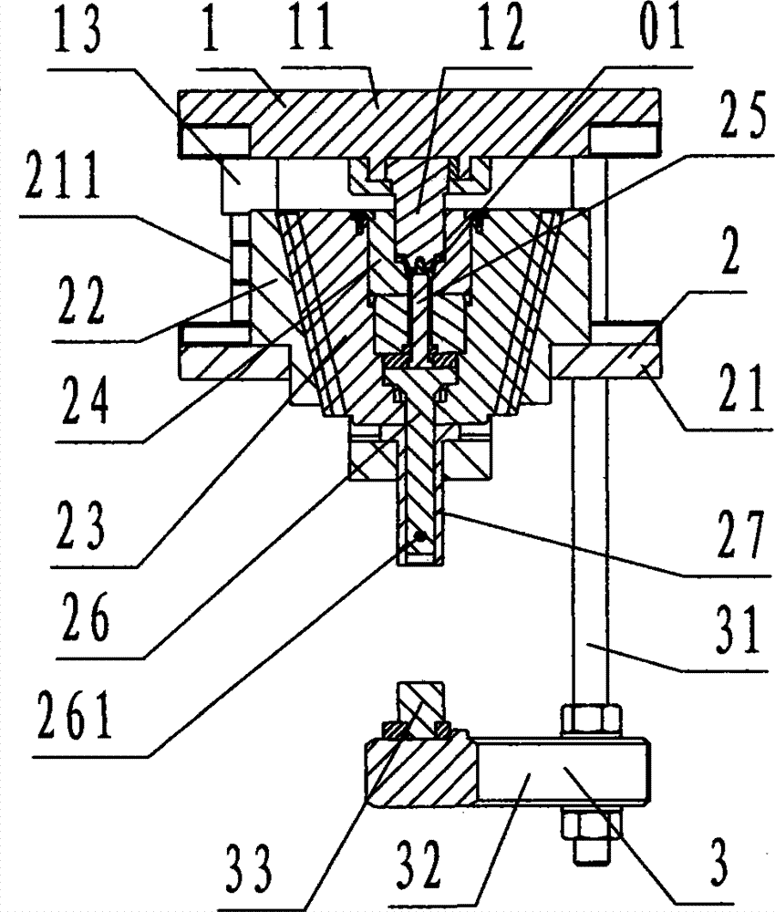
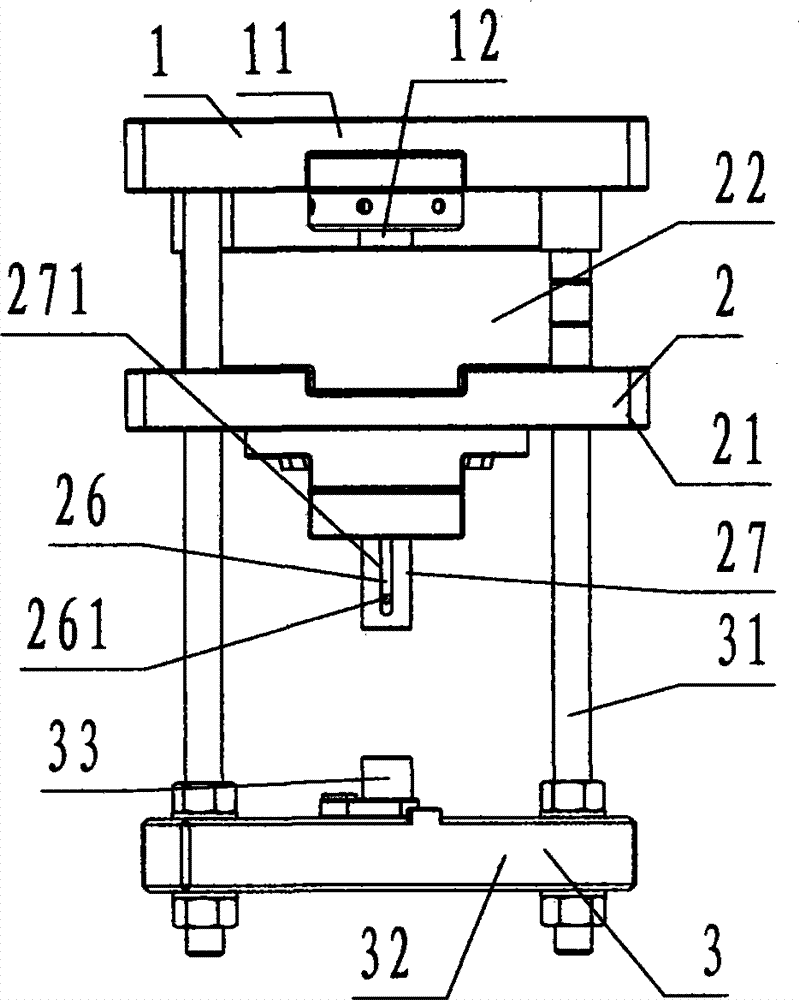
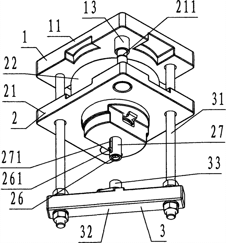
[0033] refer to Figure 1 to Figure 8, a conforming stamping and forging molding die of the present invention includes an upper die 1, a lower die 2, and a stripper 3, wherein: the upper die 1 is composed of an upper die carrier plate 11 and a core punch 12, and the The upper mold support plate 11 is a rectangular plate-shaped steel member. The two opposite corners of the upper mold support plate 11 are provided with guide sleeves 13 for cooperating with the guide pillars 211, and the other two opposite corners are provided with guide sleeves 13 for connecting pull rods 31. The step through hole is called the tie rod fixing hole; the lower center of the upper mold carrier plate 11 is provided with a downwardly protruding core punch 12, and the core punch 12 is provided on the bottom to match the shape of the upper part of the undercut product 01. Profiled cylindrical steel member;

[0034] The lower mold 2 is composed of a base 21, a guide post 211, a tapered cavity cover 22,...


PUM


Abstract

The invention discloses a half stamp forging forming die. The half stamp forging forming die comprises an upper die (1), a lower die (2) and a die ejector (3). A device formed by the parts is adopted, a core punch is arranged on the upper die, and the lower die is composed of a base, a guide column, a conical cavity sleeve, a half sliding block, a half cavity, a core rod, an ejector rod and an ejector sleeve, wherein the ejector rod is provided with a linkage pin, the ejector sleeve is provided with a delay slotted hole, and an ejector column is arranged on the die ejector. In the working process, the core punch conducts punching upwards through forging materials to make the half sliding block move downwards and concentrically contracts along a conical inner cavity of the conical cavity sleeve at the same time, and a die cavity defined by the core punch, the half cavity and the core rod is utilized to make the forging materials into a back off product through stamp forging and forming; in the die ejection process, the upper die is utilized to conduct upward reset, and the ejector column of the die ejector is driven to upwards push the ejector sleeve in an ejection mode to drive the half sliding block to move upwards. By the utilization of the technical scheme that transverse die sinking and core pulling are conducted on the half cavity through the conical cavity sleeve and the half sliding block, the back off product does not need to be secondarily cut due to the fact that the product is manufactured through stamping forging and forming, and therefore the purposes of improving efficiency and reducing cost are achieved.

Description

technical field [0001] The invention relates to a stamping and forging molding die, in particular to a conforming stamping and forging molding die for stamping and forging a valve core product of a pressure reducing valve provided with a stripping undercut structure. Background technique [0002] Stamping and forging molding dies are also called punching and forging molding dies, referred to as punching and forging dies. The upper and lower dies of the punching and forging dies in the prior art are all integral structures, so they are only suitable for stamping and forging products without stripping and undercut structures. For undercut products with a stripping undercut structure, such as the valve core of a pressure reducing valve, the existing technology adopts a punching machine and a punching die to forge a blank that is roughly the same shape as the undercut product, and then the metal cutting machine tool Cut the blank into an undercut product; because the undercut pr...

Claims


Application Information

Patent Timeline
IPC IPC(8): B21J13/02
Inventor 吴林平
Owner 宁波华平智控科技股份有限公司
Learn More