
Atomizing nozzle for urea-pyrolysis ammonia preparation process and solution atomizing device

A technology of atomizing nozzles and solution atomization, which is applied in the direction of spraying devices, spraying devices, liquid spraying devices, etc., can solve the problems of aggravating the crystallization at the bottom of the pyrolysis furnace, reducing the flow rate of atomizing air, and reducing the atomization effect, etc. Achieve the effects of reducing the atomization spray radius, increasing the air velocity, and improving the atomization efficiency

Active Publication Date: 2014-03-26
河北涿州京源热电有限责任公司
View PDF6 Cites 4 Cited by
  • Summary
  • Abstract
  • Description
  • Claims
  • Application Information

AI Technical Summary

Problems solved by technology

[0002] In the actual operation of the ammonia production process using urea pyrolysis, crystallization and blockage problems have appeared in varying degrees on the inner wall of the urea pyrolysis furnace and the bottom of the pyrolysis furnace. The main reason is that the atomization effect of the urea atomization spray gun is poor, that is, the atomization The nozzle of the spray gun does not meet the actual design requirements
Because the nozzle of the atomizing spray gun has too large coverage when spraying, the urea solution will be sprayed directly onto the inner wall of the pyrolysis furnace, forming a low temperature zone and causing crystallization; if multiple urea spray guns are running at the same time, the spray coverage of each atomizing spray gun will overlap. It is easy to form a "cross coverage" area, in which the atomized fine droplets collide with each other and merge to form larger droplets, thereby intensifying the generation of crystallization at the bottom of the pyrolysis furnace
In addition, the nozzle of the existing atomizing spray gun lacks the gas-liquid mixing area, or the volume of the mixing area is extremely small, which will greatly reduce the flow rate of the atomizing air volume during the gas-liquid mixing, thereby reducing the atomization effect

Method used


Image

  • Atomizing nozzle for urea-pyrolysis ammonia preparation process and solution atomizing device
  • Atomizing nozzle for urea-pyrolysis ammonia preparation process and solution atomizing device
  • Atomizing nozzle for urea-pyrolysis ammonia preparation process and solution atomizing device

Examples


Embodiment Construction

[0028] The present invention will be described in further detail below in conjunction with the accompanying drawings. It should be noted that the accompanying drawings are only used to explain the present invention, and are schematic descriptions of the embodiments of the present invention, but should not be construed as limiting the present invention.

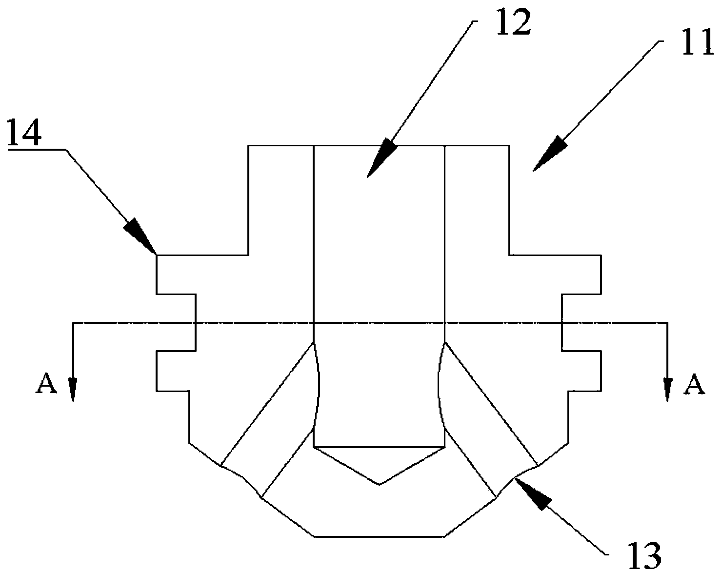
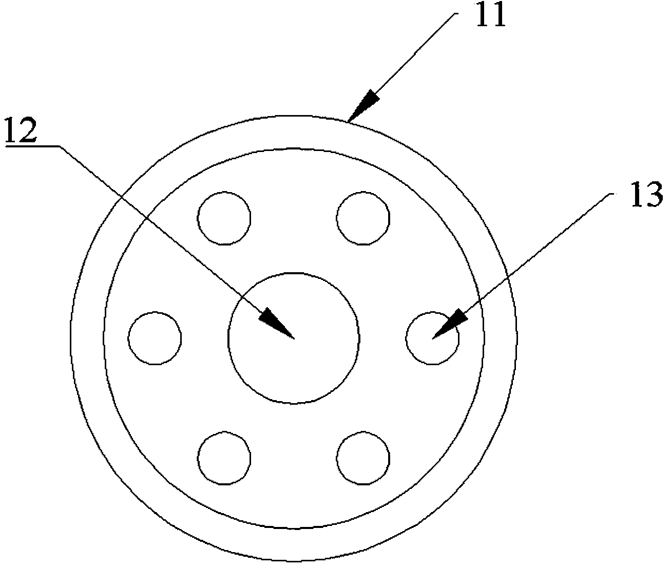
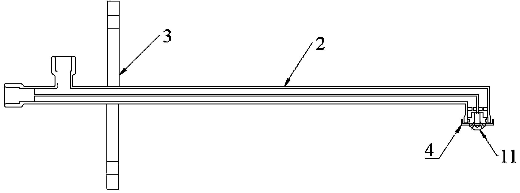
[0029] Such as figure 1 , figure 2 As shown, the atomizing nozzle of the present invention includes: a nozzle body 11, a chamber 12 is arranged on the nozzle body 11, and a plurality of injection holes 13 are arranged on the side wall of the injection end of the nozzle body 11, wherein the plurality of injection holes 13 are respectively It communicates with the chamber 12, and the angles between the multiple injection holes 13 and the central axis of the nozzle body 11 are all less than 60°, so that the spray coverage radius of the atomizing nozzle is smaller than the distance from the atomizing nozzle to the inner wall of ...


PUM


Abstract

The invention discloses an atomizing nozzle for a urea-pyrolysis ammonia preparation process. The atomizing nozzle comprises a nozzle body, a cavity arranged in the nozzle body, a plurality of spraying holes distributed in the side wall of the spraying end of the nozzle body. The spraying holes are respectively communicated with the cavity, and the angle between each spraying hole and the central axis of the nozzle body is smaller than 60 degrees. Due to the fact that the atomizing nozzle is provided with the gas-liquid mixing cavity and the angle between each spraying hole and the axis of the atomizing nozzle is decreased, the spraying covering radius of the atomizing nozzle is reduced, and crystallization caused when atomized liquid is sprayed to the inner wall of a pyrolysis device is avoided. In addition, the invention further discloses an atomizing device.

Description

technical field [0001] The invention relates to the technical field of flue gas urea denitrification, in particular to an atomizing nozzle and a solution atomizing device used in the urea pyrolysis ammonia production process. Background technique [0002] In the actual operation of the ammonia production process using urea pyrolysis, crystallization and blockage problems have appeared in varying degrees on the inner wall of the urea pyrolysis furnace and the bottom of the pyrolysis furnace. The main reason is that the atomization effect of the urea atomization spray gun is poor, that is, the atomization The nozzle of the spray gun does not meet the actual design requirements. Because the nozzle of the atomizing spray gun has too large coverage when spraying, the urea solution will be sprayed directly onto the inner wall of the pyrolysis furnace, forming a low temperature zone and causing crystallization; if multiple urea spray guns are running at the same time, the spray cov...

Claims


Application Information

Patent Timeline
Patent Type & Authority Applications(China)
IPC IPC(8): B05B1/14B05B7/04B05B15/06
CPCB05B1/14B05B7/045C01C1/086
Inventor 苏金海王斌李刚刘振生王冲康继军
Owner 河北涿州京源热电有限责任公司
Learn More