Apparatus for preventing spark propagation

A spark and top sealing technology, applied in transportation and packaging, pipes/pipe joints/fittings, aircraft lighting protectors, etc., can solve the problem of composite materials or non-conductive fuel tanks accumulating and depositing static electricity

Active Publication Date: 2014-03-19
THE BOEING CO
View PDF9 Cites 0 Cited by
  • Summary
  • Abstract
  • Description
  • Claims
  • Application Information

AI Technical Summary

Problems solved by technology

Additionally, composite or non-conductive fuel tanks may accumulate static electricity deposits as the aircraft flies through the air

Method used


Image

  • Apparatus for preventing spark propagation
  • Apparatus for preventing spark propagation
  • Apparatus for preventing spark propagation

Examples


Embodiment Construction

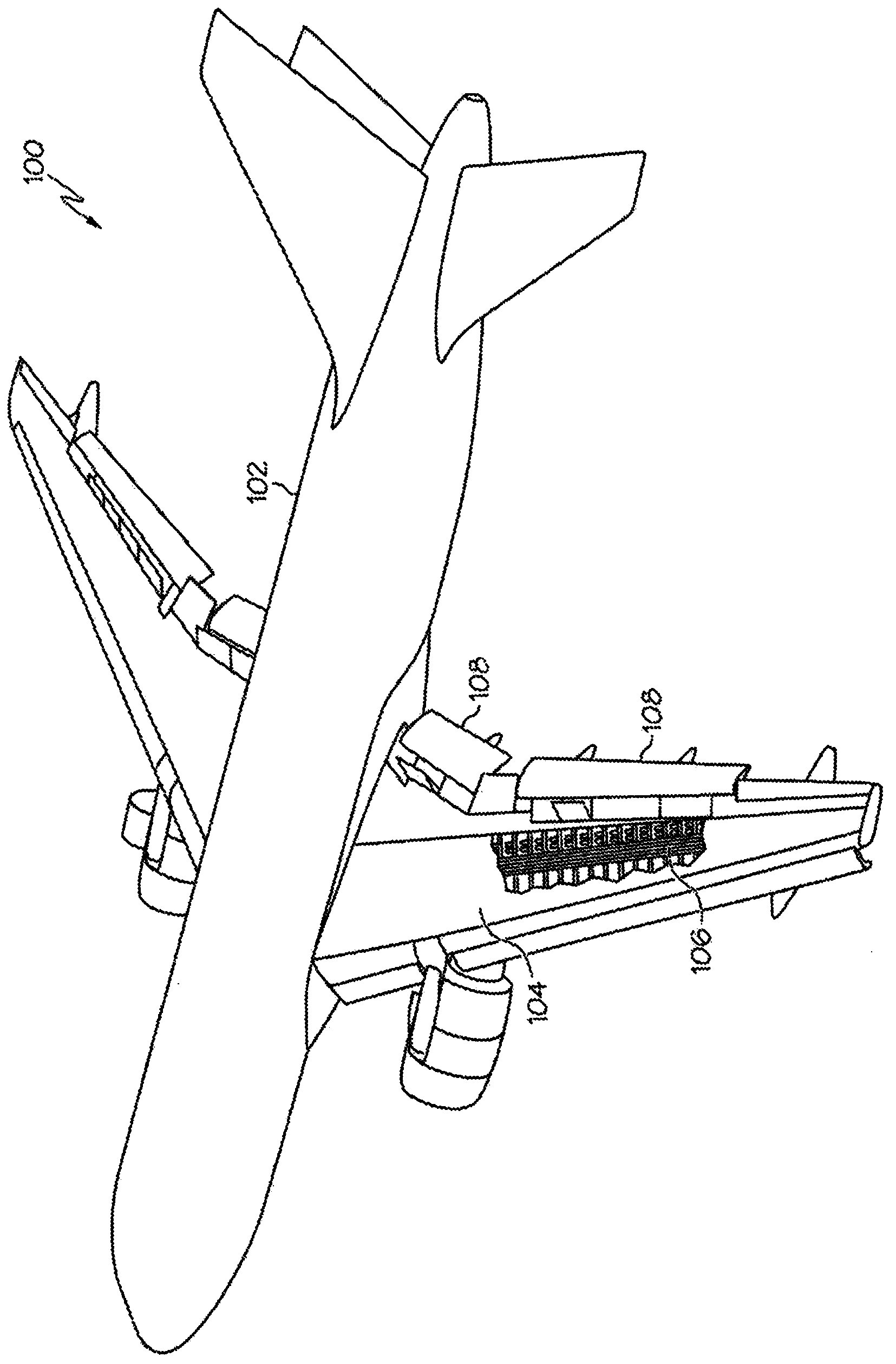
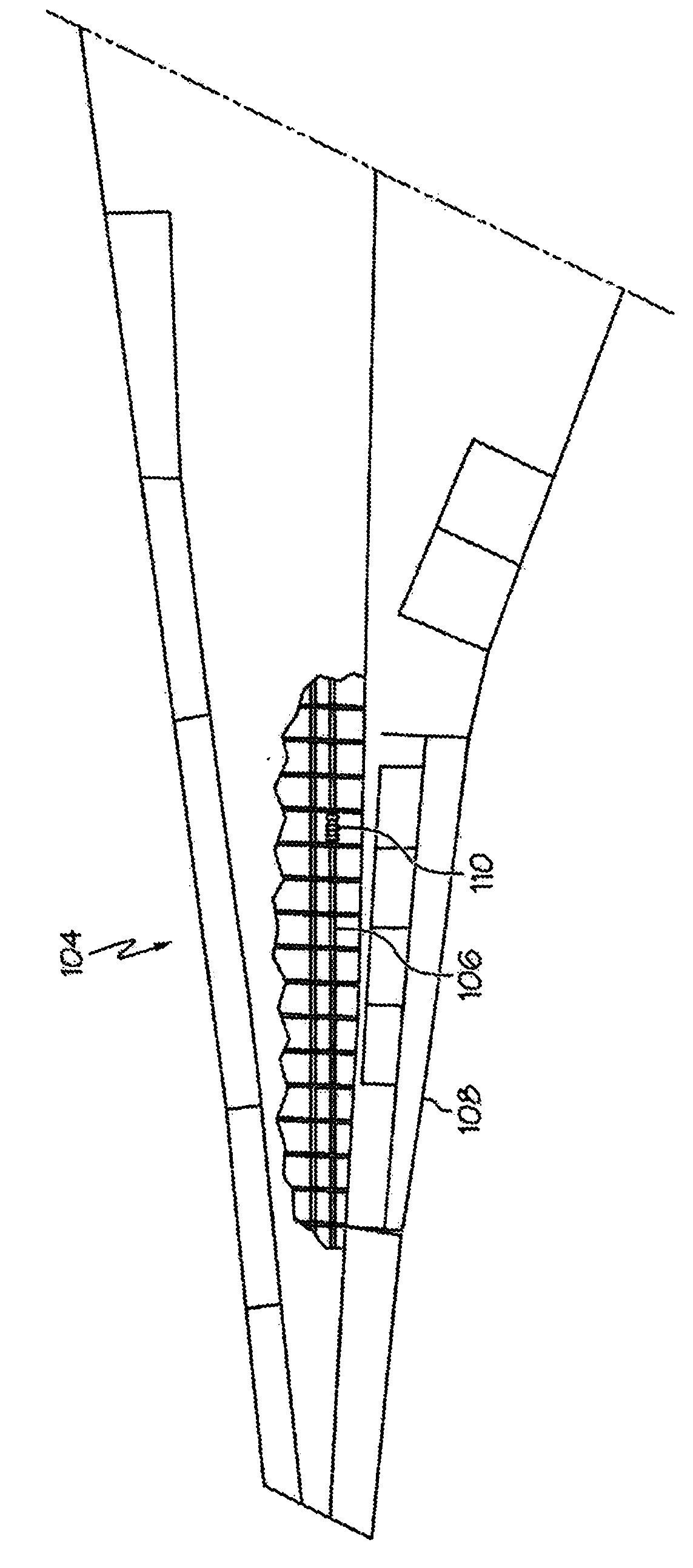
[0024] like figure 1 As shown, commercial aircraft 100 generally consists of a fuselage 102 , wings 104 including hydraulic lines 106 and flaps 108 . Flaps 108 are placed on the wings 104 to provide flight control for the aircraft. like figure 2 As shown, hydraulic lines 106 may pass through the wings 104 of the aircraft and may include one or more hydraulic connections 110 . These hydraulic lines 106 may control flaps 108 or other control structures of the aircraft.

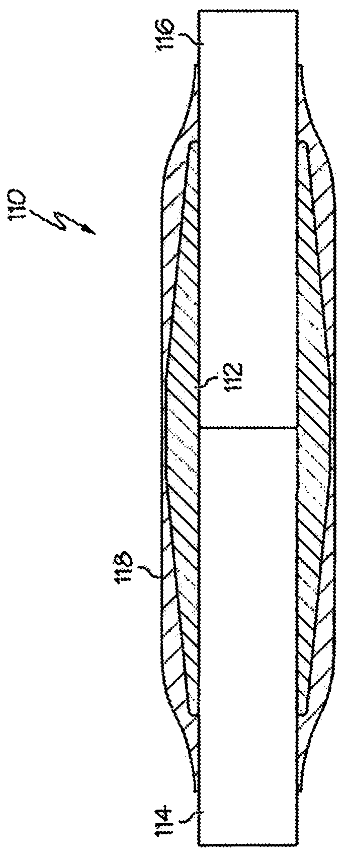
[0025] image 3 A cross-sectional view showing one embodiment of the improved device. As shown in this figure, the hydraulic connection 110 generally consists of a hydraulic fitting 112 placed generally around the hydraulic pipes 114 , 116 . In this illustration, the hydraulic fitting 112 is a connector for connecting the first section 114 of the hydraulic line 106 to the second section 116 . The first section 114 and the second section 116 of the hydraulic line 106 may be secured by swaging or any other ...


PUM


Abstract

Described herein is a novel method and apparatus for preventing spark propagation from a hydraulic joint (110) to a surrounding medium, such as a fuel source. The hydraulic joint (110) includes a fitting (112) and tubes (114, 116). A tip seal (122) may be placed about the edge of the hydraulic fitting (112) or a sleeve (118) may be placed about the joint (110), each resulting in an independent mechanical barrier between the joint (110) and surrounding medium, thereby preventing spark propagation to the surrounding medium.

Description

technical field [0001] The present disclosure relates to hydraulic joint safety devices, particularly for use in aircraft or other aircraft. Background technique [0002] In modern commercial aircraft, fuel is traditionally stored in the wings. A number of hydraulic lines may pass through the fuel storage area to power and control hydraulic power elements such as flaps. These hydraulic lines require many joints to connect various lengths of hydraulic pipes to each other, to other joints, and to bulkhead panels and to conduct hydraulic fluid. During operation of the aircraft, it is possible that electrical sparks may develop between hydraulic lines and fittings and propagate to the fuel tank, resulting in a potential source of ignition. In a number of ways to contain or prevent this risk, the present disclosure describes an optional improved method and apparatus for preventing the propagation of sparks from the fitting to the fuel tank. [0003] The Federal Aviation Admini...

Claims


Application Information

Patent Timeline
Patent Type & Authority Applications(China)
IPC IPC(8): F16L25/03B64D45/02B64D37/32
CPCB64D37/32F16L25/03B64D45/02Y10T29/49227Y10T137/0402
Inventor M·E·罗拉鲍格J·P·欧文B·A·约翰逊E·W·杜韦尔
Owner THE BOEING CO
Why Eureka
Try Eureka