Tool structure for machining end faces of high-concentricity shaft parts

A technology for shaft parts and end face processing, applied in metal processing equipment, metal processing machinery parts, positioning devices, etc., can solve the problem of inability to ensure the concentricity of parts and clamping parts, pinching or wear of shaft parts, affecting parts processing Quality and other issues, to achieve the effect of saving time and effort in layout, improving installation time, improving production efficiency and progress

Inactive Publication Date: 2014-03-19
WUXI HANGHU TECH
View PDF7 Cites 0 Cited by
  • Summary
  • Abstract
  • Description
  • Claims
  • Application Information

AI Technical Summary

Problems solved by technology

[0002] At present, the end face processing of high-precision and high-concentricity shaft parts is processed after being clamped by a chuck, but this clamping method is easy to pinch or wear the surface of the shaft parts, and this clamping method cannot Ensuring the concentricity of the parts and the clamping parts greatly affects the processing quality of the parts, improves the repair rate of the enterprise, and affects the production progress

Method used


Image

  • Tool structure for machining end faces of high-concentricity shaft parts
  • Tool structure for machining end faces of high-concentricity shaft parts
  • Tool structure for machining end faces of high-concentricity shaft parts

Examples


Embodiment Construction

[0017] The specific embodiments of the present invention will be described below in conjunction with the drawings.

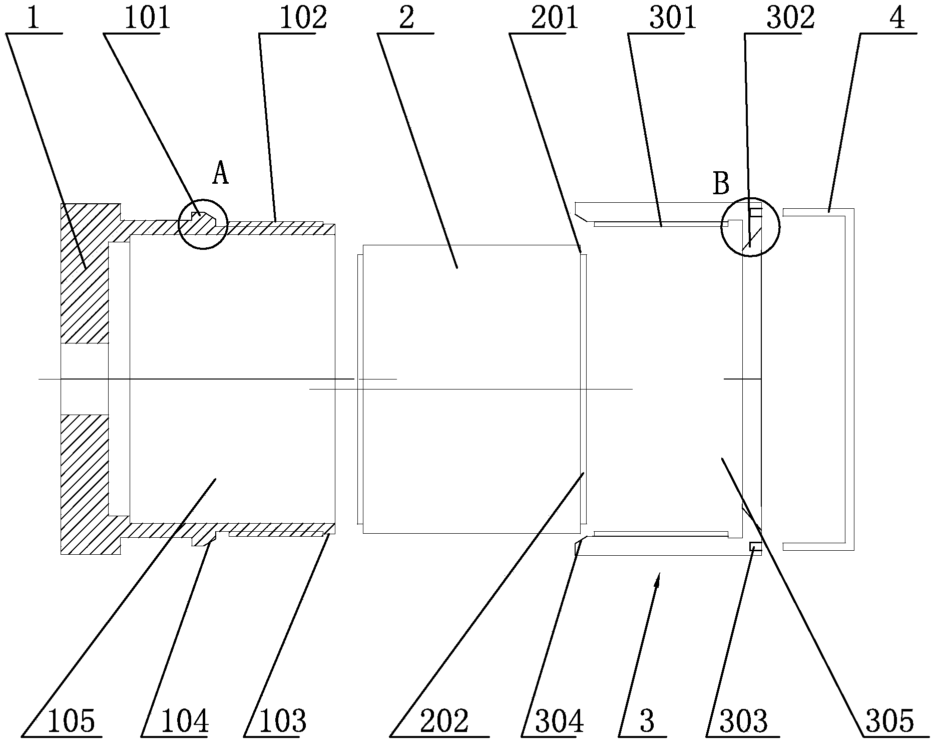
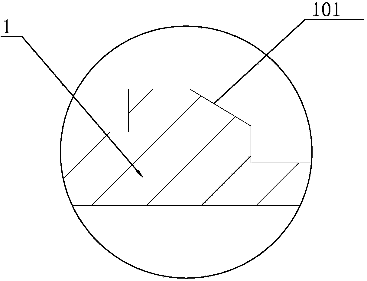
[0018] Such as figure 1 As shown, the present invention includes a positioning sleeve 1, a counterbore 105 for fitting shaft parts 2 is opened in the middle of the positioning sleeve 1, and an external thread 102 and a connecting flange 101 are provided on the outer periphery of the positioning sleeve 1, such as figure 2 As shown, a first inclined surface 104 is provided on the connecting flange 101. Such as figure 1 As shown, the rotating sleeve 3 is threadedly connected with the positioning sleeve 1. A groove 305 is opened in the middle of the rotating sleeve 3, and an internal thread 301 and a second inclined surface 304 are arranged in the groove 305, and a through hole 302 is also opened on the rotating sleeve 3. The through hole 302 is a tapered hole. An arc-shaped groove 303 is also opened on the rotating sleeve 3 so that the end of the rotating handle 4 fi...


PUM


Abstract

The invention relates to a tool structure for machining end faces of high-concentricity shaft parts. The tool structure comprises a positioning sleeve, a rotating sleeve is connected with the positioning sleeve in a threaded manner, and a rotating handle is inserted into the end of the rotating sleeve. The tool structure is simple and convenient to mount, the shaft parts are effectively and concentrically fixed by the aid of the rotating sleeve and the positioning sleeve, concentricity of the shaft parts in the machining process is ensured, time and labor are saved when the rotating handle is arranged, mounting time of the shaft parts is greatly shortened, and production efficiency and progress are improved.

Description

Technical field [0001] The invention relates to tooling, in particular to a tooling structure used for end surface processing of shaft parts with high concentricity. Background technique [0002] At present, the end face machining of high-precision, high-concentricity shaft parts is processed after clamping by a chuck, but this clamping method is easy to cause clamping or abrasion on the surface of the shaft part, and the clamping method cannot Ensuring the concentricity between the parts and the clamping parts greatly affects the processing quality of the parts, increases the repair rate of the enterprise, and affects the production schedule. Summary of the invention [0003] In view of the above-mentioned existing problems, the applicant has conducted research and improvement, and provided a tooling structure for the end face processing of high concentricity shaft parts, which has stable clamping, ensures the concentricity of the parts and the clamping parts, and greatly improve...

Claims


Application Information

Patent Timeline
Patent Type & Authority Applications(China)
IPC IPC(8): B23Q3/00
CPCB23Q3/00
Inventor 范罗荣
Owner WUXI HANGHU TECH
Why Eureka
Try Eureka