
Tree transplanter

A tree transplanting and frame technology, applied in the field of machinery, can solve the problems of affecting the survival rate of tree transplanting, damage to the root system of nearby trees, easy damage to the tree body and tree crown, etc., to save manpower, low labor intensity, and ditching high efficiency effect

Inactive Publication Date: 2014-03-19
杜会森
View PDF9 Cites 13 Cited by
  • Summary
  • Abstract
  • Description
  • Claims
  • Application Information

AI Technical Summary

Problems solved by technology

However, although the excavator is powerful, its digging speed is not fast, and the bucket of the excavator is suitable for digging soil, but it is not suitable for cutting off tree roots. It is more difficult to dig out the thick roots of large seedlings, and it is easy to cause the main root system of the tree to be pulled broken, seriously affecting the survival rate of tree transplanting
During the excavation process, a large excavation pit will be formed around the tree, which will easily damage the tree body and crown, as well as the root system of nearby trees, and cause great damage to surrounding plants.

Method used


Image

  • Tree transplanter
  • Tree transplanter
  • Tree transplanter

Examples


Embodiment 1

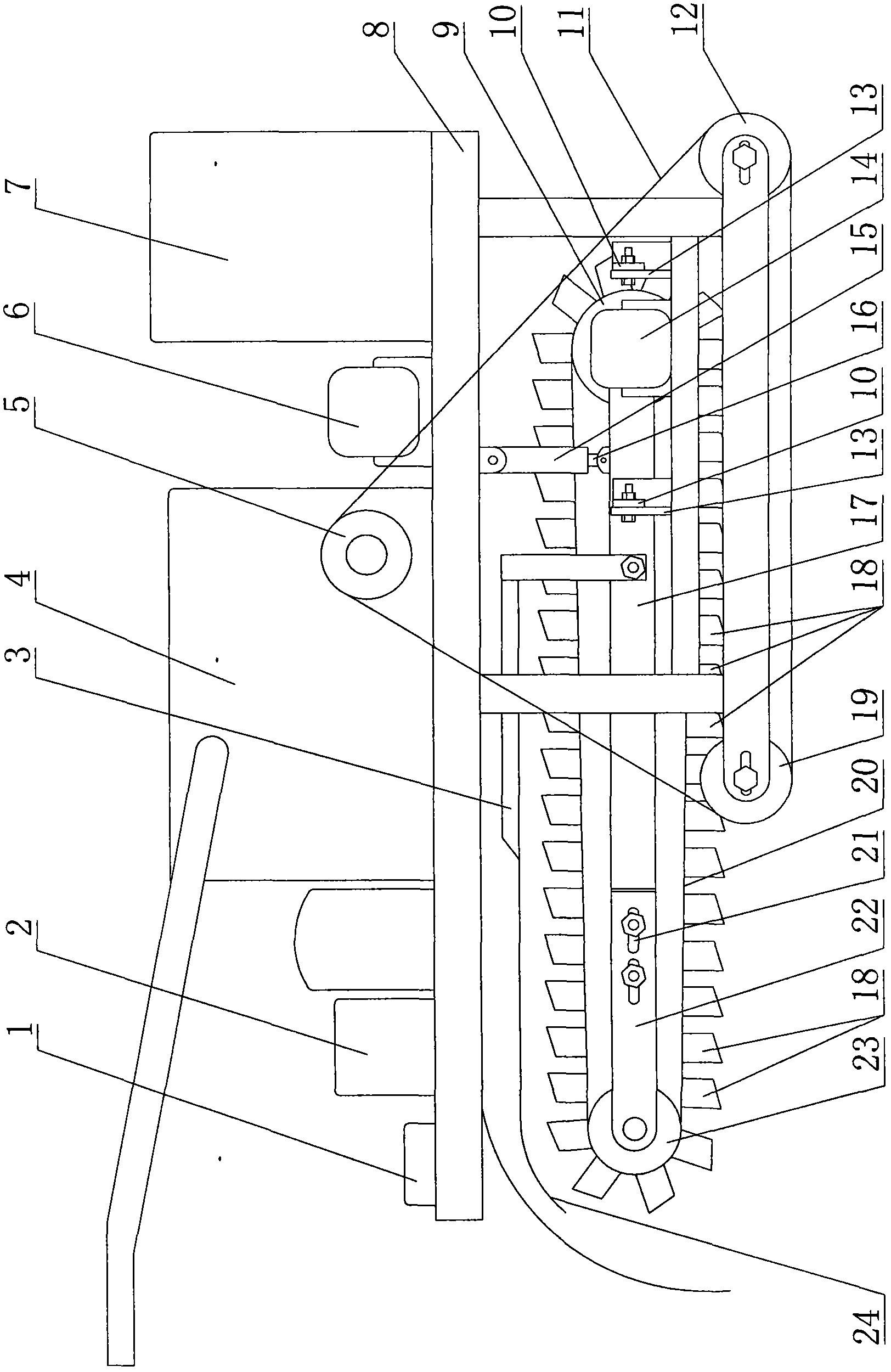
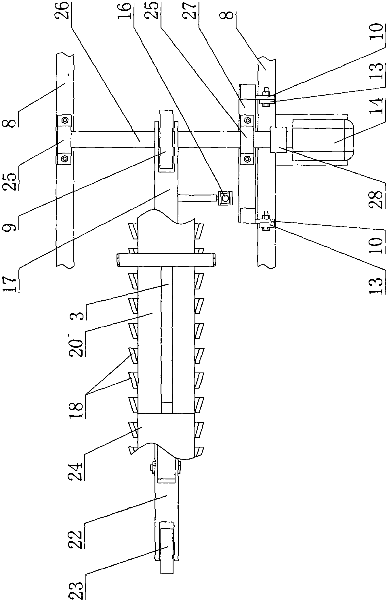
[0022] Embodiment 1: as attached figure 1 And attached figure 2 Shown, tree transplanting machine comprises frame 8, is connected with motor 7, oil tank, oil pump 2, gearbox 4 and traveling mechanism on frame 8, and hydraulic cylinder 15 is installed on frame 8, and the bottom of frame 8 is connected There is a connecting frame 27 that can rotate relative to the frame 8, the connecting frame 27 is connected with a cutting arm, the piston rod 16 of the hydraulic cylinder 15 is hinged with the cutting arm, one end of the cutting arm is provided with a drive wheel 9, and the other end of the cutting arm is provided with The driven wheel 23, the driving wheel 9 and the driven wheel 23 are sheathed with a chain 20, the chain 20 is equipped with a cutting knife 18, and the driving wheel 9 is transmission-connected with a cutting hydraulic motor 14. The hydraulic cylinder 15 and the cutting hydraulic motor 14 are connected with a hydraulic switch device 1 . The hydraulic switch de...

Embodiment 2

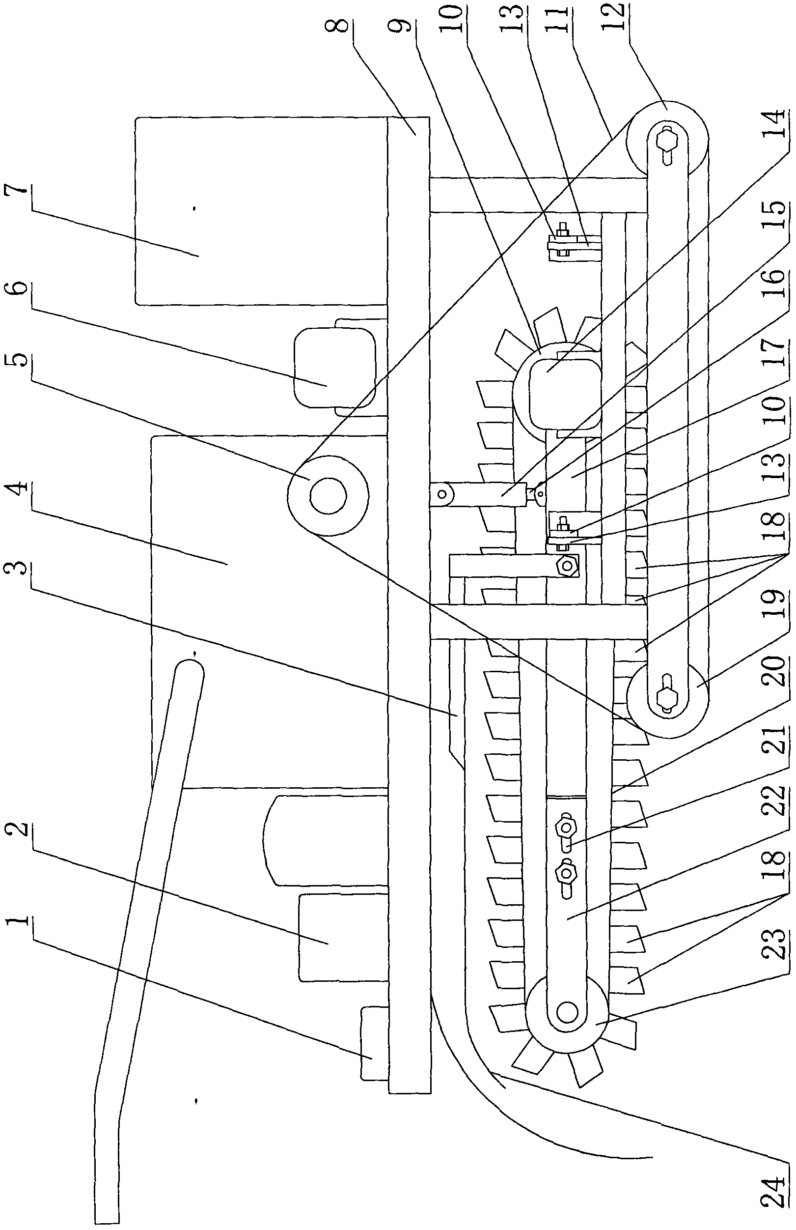
[0029] Embodiment 2: as attached image 3 And attached Figure 4 Shown, tree transplanting machine comprises frame 8, is connected with motor 7, oil tank, oil pump 2, gearbox 4 and traveling mechanism on frame 8, and hydraulic cylinder 15 is installed on frame 8, and the bottom of frame 8 is connected There is a connecting frame 27 that can rotate relative to the frame 8, the connecting frame 27 is connected with a cutting arm, the piston rod 16 of the hydraulic cylinder 15 is hinged with the cutting arm, one end of the cutting arm is provided with a drive wheel 9, and the other end of the cutting arm is provided with The driven wheel 23, the driving wheel 9 and the driven wheel 23 are sheathed with a chain 20, the chain 20 is equipped with a cutting knife 18, and the driving wheel 9 is transmission-connected with a cutting hydraulic motor 14. The hydraulic cylinder 15 and the cutting hydraulic motor 14 are connected with a hydraulic switch device 1 . The hydraulic switch de...


PUM


Abstract

The invention discloses a tree transplanter. The tree transplanter comprises a rack, and an engine, an oil pump and a walking mechanism are connected to the rack. The tree transplanter is characterized in that a hydraulic cylinder is installed on the rack, a connecting frame capable of rotating relative to the rack is connected to the lower portion of the rack, a cutting arm is connected to the connecting frame, a piston rod of the hydraulic cylinder is hinged to the cutting arm, a driving wheel is arranged at one end of the cutting arm, a driven wheel is arranged at the other end of the cutting arm, the driving wheel and the driven wheel are sleeved with a chain, a cutting knife is installed on the chain, and a cutting hydraulic motor is in transmission connection with the driving wheel. The tree transplanter has the advantages of being reasonable in design, simple in structure, stable in work, high in ditching efficiency, low in labor intensity and convenient to maintain and saving manpower.

Description

technical field [0001] The invention relates to a machine, in particular to a tree transplanting machine. Background technique [0002] With the requirements of urban greening, the transplanting of large seedlings also increases rapidly. But because large seedlings have been grown for many years, the root system is relatively developed, the roots are very thick, and often interlaced, so it is very troublesome to dig out manually. Therefore, excavating large seedlings is one of the most labor-intensive tasks. For this reason, many companies choose to use high-powered excavators to dig around the roots of trees. However, although the excavator is powerful, its digging speed is not fast, and the bucket of the excavator is suitable for digging soil, but it is not suitable for cutting off tree roots. It is more difficult to dig out the thick roots of large seedlings, and it is easy to cause the main root system of the tree to be pulled broken, has a strong impact on the surviv...

Claims


Application Information

Patent Timeline
Patent Type & Authority Applications(China)
IPC IPC(8): A01G23/04
Inventor 马提阔杜会森
Owner 杜会森
Learn More