Work simulation device and method

A technology of simulation device and processed object, applied in program control, instrument, computer-aided design, etc., can solve the problems of unverifiable operation, cost, long waiting time, etc., and achieve the effect of high-efficiency repeated processing simulation

Active Publication Date: 2014-03-12
MITSUBISHI ELECTRIC CORP
View PDF4 Cites 2 Cited by
  • Summary
  • Abstract
  • Description
  • Claims
  • Application Information

AI Technical Summary

Problems solved by technology

However, in the case of performing machining simulation to find out problematic points in machining, there may often arise a problem that machining simulation must be repeatedly performed in order to analyze its cause or take countermeasu...

Method used


Image

  • Work simulation device and method
  • Work simulation device and method
  • Work simulation device and method

Examples


Embodiment approach 1

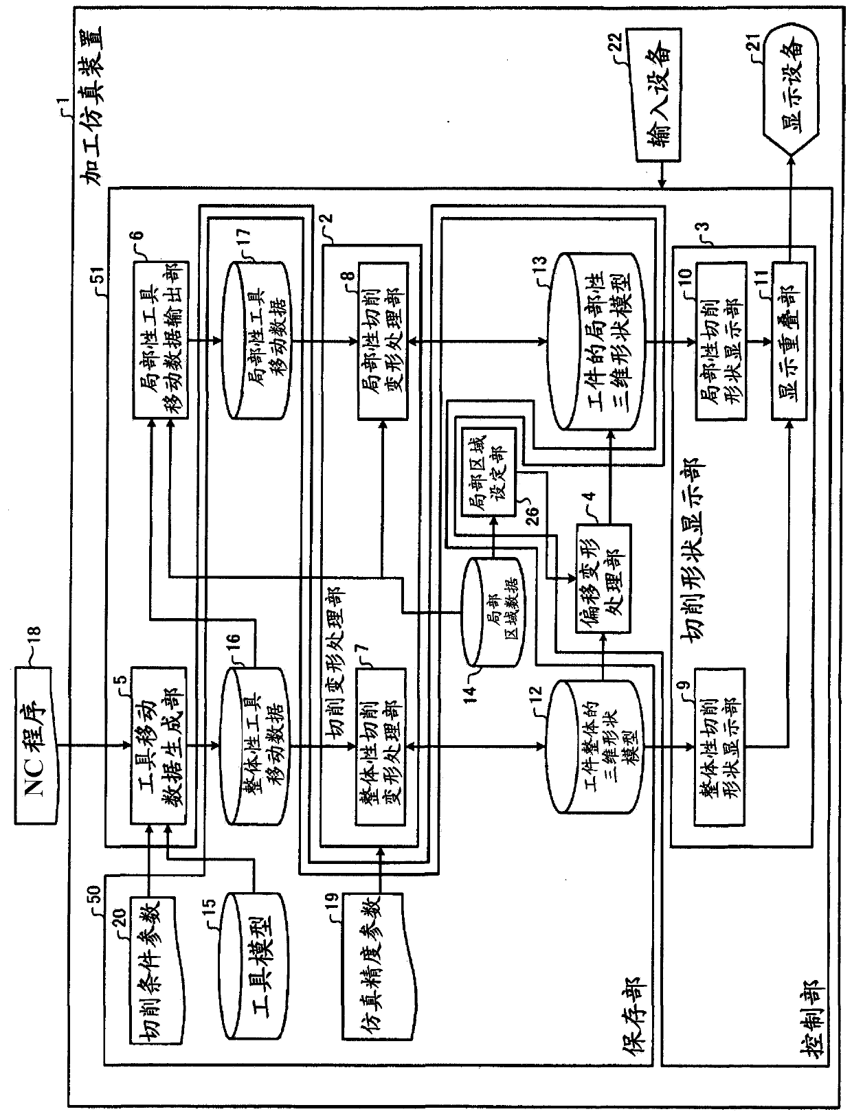
[0023] figure 1 It is a figure which shows the structure of Embodiment 1 of the processing simulation apparatus of this invention. The processing simulation device 1 includes: a storage unit 50 for storing the overall three-dimensional shape model 12 of the workpiece (processed object), a local three-dimensional shape model 13 of the workpiece, local area data 14, and a tool model 15; Deformation processing part 2, cutting shape display part 3, offset deformation processing part 4, tool movement data generation part 5, localized tool movement data output part 6 and other functional parts. The machining simulation device 1 simulates machining of the workpiece by cutting and deforming the three-dimensional shape model of the workpiece based on the tool model 15 and movement trajectory data representing the movement trajectory of the tool, and displaying the three-dimensional shape model of the workpiece after cutting and deformation. The control unit 51 is a processing device i...

Embodiment approach 2

[0056] Figure 4 It is a figure which shows the structure of Embodiment 2 of the processing simulation apparatus of this invention. In the present embodiment, in the machining simulation device 23, the local tool movement data output unit 24 operates differently from the local tool movement data output unit 6 in Embodiment 1, and additionally includes a new storage tool Move the unit that holds data 25. Other data and individual operations of the processing unit are the same as in the first embodiment.

[0057] When the local tool movement data output unit 24 executes the processing simulation for the first time, according to the preset local region data 14, the tool model in the global tool movement data 16 passes through the region of the local region data 14. The tool movement data is cumulatively stored in the localized tool movement storage data 25 . Then, in the second and subsequent machining simulations, the tool movement data stored in the localized tool movement s...


PUM


Abstract

Provided is a work simulation device, comprising: a local region setting unit (26) which sets a local region in a workpiece; an offset transform processing unit (4) which offset transforms, among a workpiece overall 3-D shape model (12), a shape of a portion wherein a local region is set, generating a workpiece local 3-D shape model (13); a local tool movement data output unit (6) which outputs local tool movement data (17) from overall tool movement data (16) based on a tool model (15) and tool movement trajectory data; a local cutting transform processing unit (8) which carries out a cutting transformation of the workpiece local 3-D shape model (13) on the basis of the local tool movement data (17); and a display superposition unit (11) which superpositions the cutting transformed workpiece local 3-D shape model (13) upon the workpiece overall 3-D shape model (12) and displays same.

Description

technical field [0001] The present invention relates to cutting processing using an NC (Numerical Control: numerical control) machine tool, and to a processing simulation device and method for converting the shape of a workpiece (processed object) represented by a three-dimensional shape model according to a tool model and its movement trajectory To perform cutting deformation, and display the resulting shape graphically, thereby simulating the cutting process of the workpiece on the computer. Background technique [0002] When cutting using an NC machine tool, machining simulation is widely used to verify whether a desired shape can be machined correctly using a prepared NC program. However, in the case of performing machining simulation to find out problematic points in machining, there may often arise a problem that machining simulation must be repeatedly executed in order to analyze the cause or take countermeasures. [0003] In the cutting process, the workpiece starts...

Claims


Application Information

Patent Timeline
IPC IPC(8): G05B19/4069
CPCG05B2219/35349G06F17/5086G05B19/4069G06F30/17
Inventor 宮田亮
Owner MITSUBISHI ELECTRIC CORP
Why Eureka
Try Eureka