Insertion optic fiber communication realization device based on satellite time base signal
A time-based signal, optical fiber communication technology, applied in multiplexing communication, time-division multiplexing system, electrical components, etc., can solve the problem of inability to transmit data remotely synchronously, and achieve the effect of synchronous communication
- Summary
- Abstract
- Description
- Claims
- Application Information
AI Technical Summary
Problems solved by technology
Method used
Image

Examples
example 1
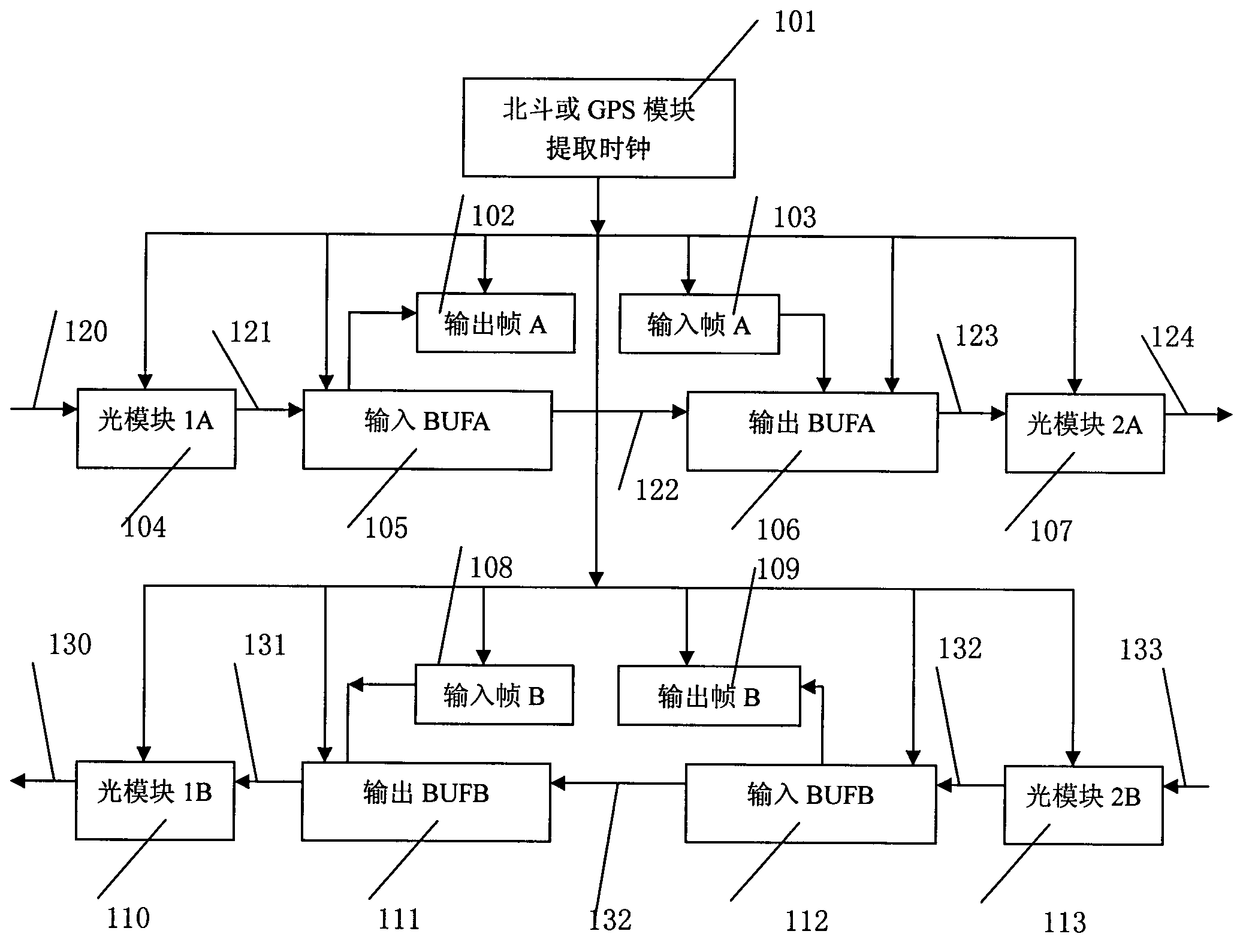
[0024] Preferred example 1: such as figure 1 Shown is a schematic block diagram of the device based on satellite time-base signal insertion optical fiber communication,
[0025] Beidou or GPS module extract clock (101);
[0026] Uplink channel consists of: optical fiber (120), interface (121), output frame A (102), input frame A (103), interface (122), optical module 1A (104), input BUFA (105), output BUFA (106 ), an interface (123), an optical module 2A (107), and an optical fiber (124);
[0027] The downlink channel consists of: optical fiber (133), optical module 2B (113), interface (132), input BUFB (112), interface (132), output BUFB (111), interface (131), optical module 1B (110), The output frame B (109), the input frame B (108), and the optical fiber (130) are composed.
example 2
[0029] The Beidou or GPS module extracts the clock (101), and synchronously outputs the clock signal to output frame A (102), input frame A (103), optical module 1A (104), input BUFA (105), output BUFA (106), optical Module 2A (107);
[0030] The Beidou or GPS module extracts the clock (101), synchronously outputs the clock signal to optical module 2B (113), inputs BUFB (112), outputs BUFB (111), optical module 1B (110), outputs frame B (109), and inputs frame B(108);
[0031] The Beidou or GPS module extracts the clock (101) signal so that the uplink channel consists of: output frame A (102), input frame A (103), optical module 1A (104), input BUFA (105), output BUFA (106), optical module Synchronous processing of each module of 2A (107), synchronous input and output;
[0032] The Beidou or GPS module extracts the clock (101) signal so that the downlink channel is composed of: optical module 2B (113), input BUFB (112), output BUFB (111), optical module 1B (110), output fram...
example 3
[0034] The optical fiber (120) is connected to the optical module 1A (104); the optical module 1A (104) is connected to the input BUFA (105); the input BUFA (105) processes the data sent by the optical module 1A (104), and decodes it according to the module ID , if it is the data of this channel, transmit the data to the output frame A (102), and at the same time clear the corresponding position in the input BUFA, if it is not the data of this channel, then keep the data intact and continue to transmit the data;
[0035]Input BUFA (105) outputs data to output BUFA (106), and input frame A (103) inserts the data to be exported into the time slot that output BUFA (106) leaves for this unit; Extract clock (101) in Beidou or GPS module ) signal under the synchronization of the output BUFA (106) data output to the optical module 2A (107); the optical module 2A (107) is converted into an optical fiber signal and output by the optical fiber (124).
PUM
 Abstract
Description
Claims
Application Information
 - R&D
- Intellectual Property
- Life Sciences
- Materials
- Tech Scout
- Unparalleled Data Quality
- Higher Quality Content
- 60% Fewer Hallucinations
Browse by: Latest US Patents, China's latest patents, Technical Efficacy Thesaurus, Application Domain, Technology Topic, Popular Technical Reports.
© 2025 PatSnap. All rights reserved.Legal|Privacy policy|Modern Slavery Act Transparency Statement|Sitemap|About US| Contact US: help@patsnap.com