Cooling device for annular cooling machine and annular cooling machine

A technology of annular coolers and cooling devices, which is applied in the field of material cooling devices and can solve problems such as powder leakage

Inactive Publication Date: 2014-03-12
高玉宗
View PDF6 Cites 4 Cited by
  • Summary
  • Abstract
  • Description
  • Claims
  • Application Information

AI Technical Summary

Problems solved by technology

[0004] In order to solve the problem of air pollution caused by the leakage of powder in the material and the energy consumption of the cooling fan caused by the application of the cooling device in the prior art, the present invention provides a cooling device for an annular cooler, the cooling device uses air in whole or in part. As a cold air source, energy saving, and at the same time, the external pressure of the annular cooler is lower than the internal pressure, that is, negative pressure operation, which effectively solves the problem of powder leakage in the material

Method used


Image

  • Cooling device for annular cooling machine and annular cooling machine
  • Cooling device for annular cooling machine and annular cooling machine
  • Cooling device for annular cooling machine and annular cooling machine

Examples


Embodiment 1

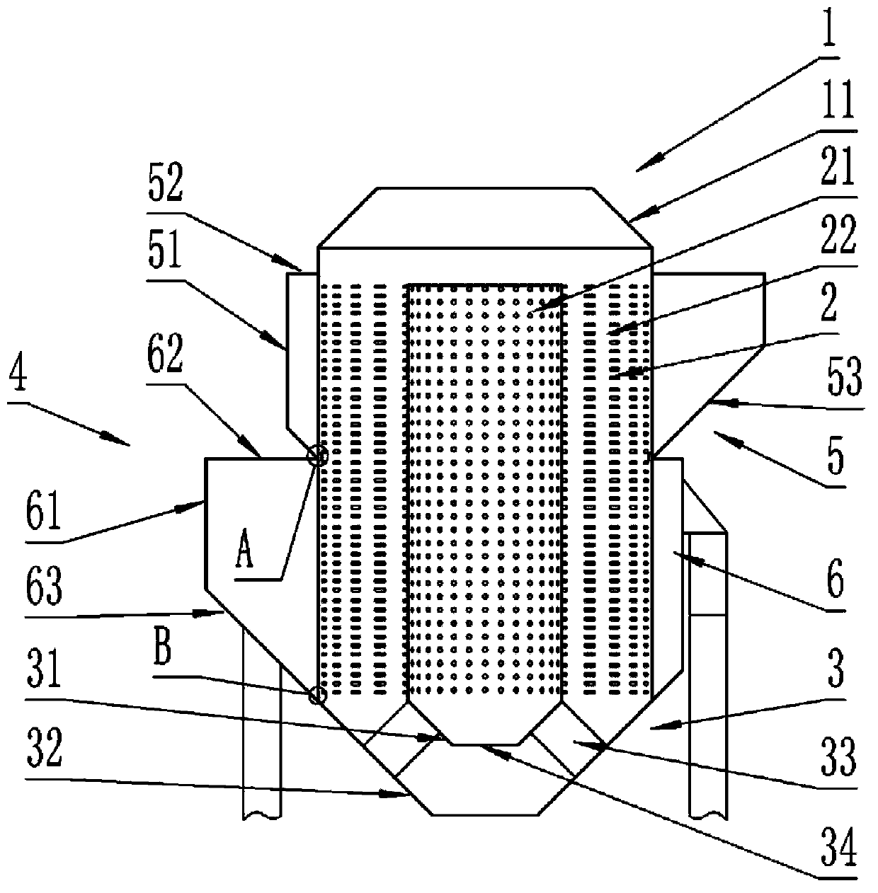
[0041] refer to figure 1 and figure 2 , are the structural schematic view and top view of the annular cooler with cooling device of the present invention, respectively. The annular cooler includes a feeding device 1, an annular material passage 2, a discharging device 3 and a cooling device 4. The material enters from the feeding device 1 and is discharged from the discharging device 3 after passing through the annular material passage 2. The cooling device 4 is used for Cool the material in the annular material channel 2.

[0042] The feeding device 1 includes a hollow structure and the top sealing end of the inner cylinder, the upper end of the hollow structure 11 is the upper opening for material entry, the lower end of the hollow structure and the top of the outer cylinder 22 are aligned in the circumferential direction. Fixed connection. The sealing end of the top of the inner cylinder 21 can be a plane structure; or a conical side of a conical structure, wherein the ...

Embodiment 2

[0055] The difference between embodiment 2 and embodiment 1 is that: the sealed exhaust chamber on the upper outside of the outer cylinder body 22 is replaced by a sealed air supply chamber, which is an annular closed space covering the ventilation holes of the outer cylinder body. The air chamber is provided with an air inlet, and the air inlet is connected with the cold air source (cooler), and the cold air source enters the annular material channel through the air inlet and the ventilation hole on the outer cylinder, and the hot air after heat exchange with the material can pass through the upper part of the annular material channel. The opening returns to the upper device (such as: rotary kiln) for reuse, and the dust generated can also return to the upper device (such as: rotary kiln) with the hot air, and the dust that enters the inner cavity of the inner cylinder 21 can be opened from the bottom of the inner hopper Terminal 34 discharges.

Embodiment 3

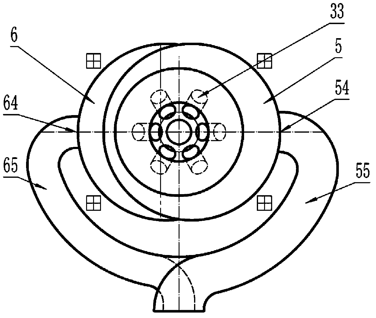
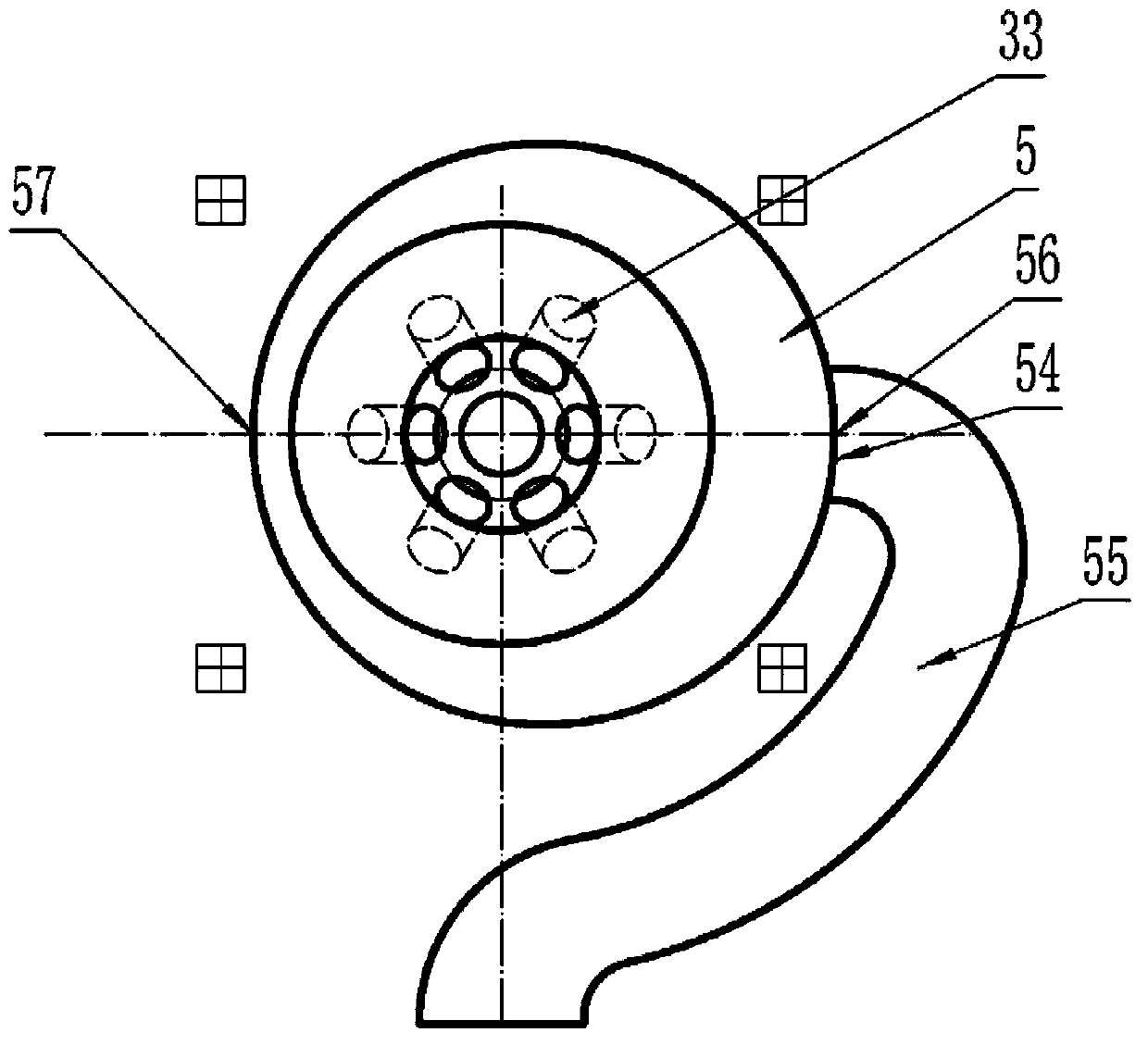
[0057] The difference between Embodiment 3 and Embodiments 1 and 2 is that, for each sealed exhaust chamber, more than one air outlet can be provided, and each air outlet is connected with an exhaust fan to extract air from different air outlets. Preferably, for a sealed exhaust chamber, a plurality of exhaust ports are evenly distributed along the circumference to ensure uniform cooling of the material. Another preference is that all the air outlets of each sealed air chamber are evenly distributed along the circumference, which also ensures that the material is cooled evenly.


PUM


Abstract

To solve the problems that when cooling devices in the prior art are used, powder in materials leaks to cause air pollution and air coolers consume energy, the invention provides a cooling device for an annular cooling machine. The cooling device comprises one or more sealed air suction chambers which are arranged outside an outer cylinder body, each sealed air suction chamber comprises a side wall, an upper cover and a lower cover, all ventilation holes or the ventilation holes in the lower portion of the outer cylinder body are covered with annular sealed spaces formed by the upper covers, the lower covers, the side walls and the outer cylinder body, the side wall of each sealed air suction chamber is provided with one or more air suction openings, and the air suction openings are used for being communicated with a suction fan in a sealed mode. The whole or part of the cooling device uses air as a cold air source, and energy is saved; meanwhile, the intensity of external pressure of the annular cooling machine is less than the intensity of internal pressure of the annular cooling machine, namely negative pressure operation is conducted, and the problem that the powder in the materials leaks is solved effectively.

Description

technical field [0001] The invention relates to a material cooling device, in particular to a cooling device for an annular cooler and an annular cooler using the cooling device. Background technique [0002] The cooling machine is an indispensable and important equipment in the calcining system of metallurgy, chemical industry and cement building materials. Its main function is to cool the hot material to the temperature allowed by the subsequent conveying, storage and grinding processes according to the process requirements, so as to ensure normal continuous production; at the same time, the cooler is also a heat exchange device, which requires the cooling of all materials in the material. The heat contained is recovered and utilized to the maximum extent to improve the thermal efficiency of the system. [0003] The cooling method of the existing annular cooler is to blow cold air into the material layer of the annular cooler by the cooling fan, and cool the material thro...

Claims


Application Information

Patent Timeline
IPC IPC(8): F27D15/02
Inventor 高玉宗
Owner 高玉宗
Why Eureka
Try Eureka