buffer feed bin
A feeding bin and buffering technology, applied in the field of material storage, can solve the problems of unsolvable materials, increase equipment cost, large frictional resistance, etc., achieve the effect of improving volumetric efficiency, eliminating dead zone of discharging, and preventing the reduction of feeding function
- Summary
- Abstract
- Description
- Claims
- Application Information
AI Technical Summary
Problems solved by technology
Method used
Image
Examples
Embodiment 1
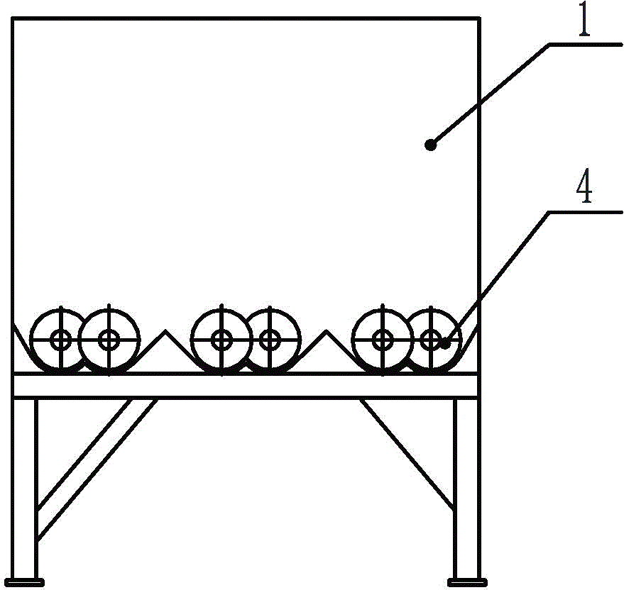
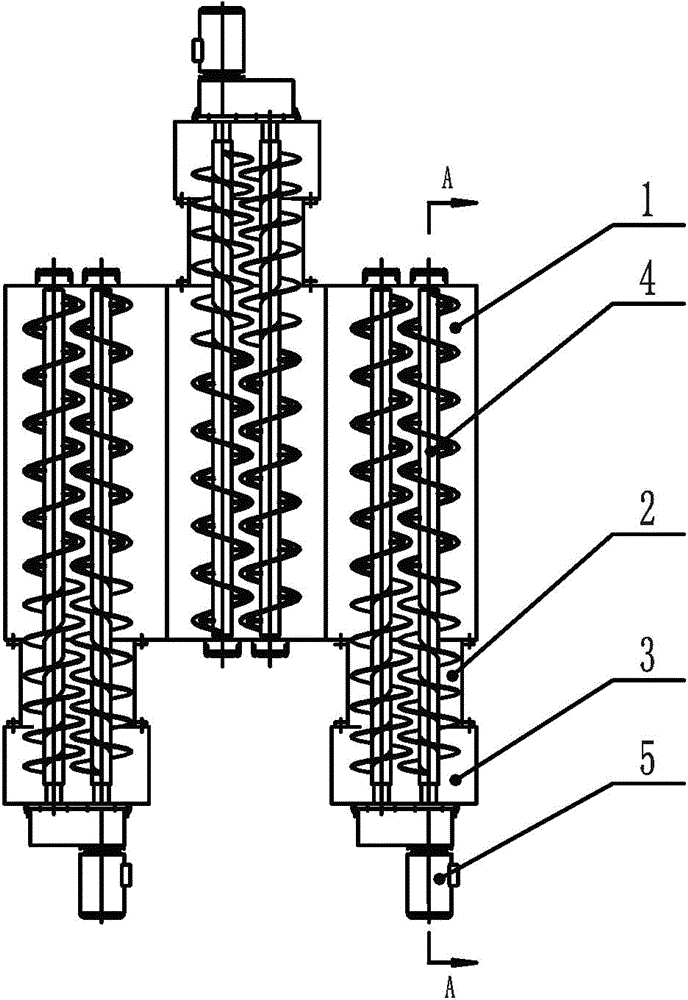
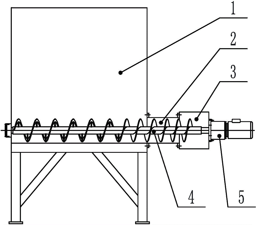
[0051] see Figure 1-3 , which shows a buffer feed bin of a preferred embodiment of the present invention. The buffer feed bin includes: a storage bin body 1; a discharge pipe body 2, which is arranged on the side wall of the storage bin body 1; a discharge hopper 3; The body 1 is connected and communicated; the discharge screw unit 4 is arranged in the storage bin body 1, the discharge pipe body 2 and the discharge hopper 3, and is used to push the material in the storage bin body to the discharge hopper 3; and The output screw unit driving mechanism 5 is connected with the output screw unit 4 to drive the output screw unit 4 to rotate.
[0052] Preferably, two or all of the storage bin body, the discharge pipe body 2 and the discharge hopper 3 are integrally structured.
[0053]Preferably, the number of the discharge pipe body 2 is two or more, each discharge pipe body 2 has two or more discharge screw units 4, each discharge pipe body 2 Each discharge screw unit 4 inside...
Embodiment 2
[0067] See you again Figure 1-3 , which shows a schematic diagram of a buffer feed bin in a preferred embodiment of the present invention. The buffer feed bin of this preferred embodiment may include: a storage bin body 1 for storing materials; a discharge screw unit (hereinafter referred to as "discharge screw") 4 for pushing materials; Spiral discharge pipe body (hereinafter specifically defined as "discharge spiral pipe") 2; discharge hopper 3 for discharge; discharge screw unit drive mechanism for driving the discharge screw rotation (hereinafter referred to as "discharge spiral pipe") 2; Discharge screw drive mechanism") 5; the discharge spiral tube 2 is located at the bottom of the storage bin body 1 and is connected to the storage bin body 1 and the discharge hopper 3 respectively, or the storage bin body 1 and the discharge spiral tube 2 and two or all of the discharge hopper 3 are integral structures; the discharge screw 4 is located in the storage bin body 1, the d...
Embodiment 3
[0084] see Figure 4-6 , which shows a schematic diagram of a buffer feeding silo in another preferred embodiment of the present invention. The buffer feed bin of this preferred embodiment includes: a storage bin body 1 for storing materials; a discharge screw 4 for pushing materials; a discharge spiral tube 2 for sealing a part of the discharge screw; as a discharge flow The discharge hopper 3 of the road; the discharge screw drive mechanism 5 for driving the discharge screw to rotate; the discharge spiral tube 2 is located at the bottom of the storage bin body 1 and is connected to the storage bin body 1 and the discharge hopper 3 respectively Connected; the discharge screw 4 is located in the storage bin body 1, the discharge spiral tube 2 and the discharge hopper 3; the power output end of the discharge screw drive mechanism 5 that drives the discharge screw is connected to the discharge The feed screw 4 is connected and can drive the discharge screw 4 to rotate.
[0085...
PUM
 Abstract
Description
Claims
Application Information
 - R&D
- Intellectual Property
- Life Sciences
- Materials
- Tech Scout
- Unparalleled Data Quality
- Higher Quality Content
- 60% Fewer Hallucinations
Browse by: Latest US Patents, China's latest patents, Technical Efficacy Thesaurus, Application Domain, Technology Topic, Popular Technical Reports.
© 2025 PatSnap. All rights reserved.Legal|Privacy policy|Modern Slavery Act Transparency Statement|Sitemap|About US| Contact US: help@patsnap.com


