Slow cooling device and method for steel plates

A slow cooling device and steel plate technology, applied in metal processing equipment, metal rolling, manufacturing tools, etc., can solve the problems of difficult timing of lifting out steel plates, expensive construction of insulation pits, increased maintenance and repair costs, etc., to achieve Eliminate white spot defects, avoid maintenance and repair costs, and achieve the effect of timely connection

Active Publication Date: 2014-03-05
INNER MONGOLIA BAOTOU STEEL UNION
View PDF6 Cites 5 Cited by
  • Summary
  • Abstract
  • Description
  • Claims
  • Application Information

AI Technical Summary

Problems solved by technology

[0005] The construction cost of the insulation pit is expensive, the location is fixed and the mobility is not strong, and the insulation material is exposed and easy to fall off, resulting in irregular replacement, which increases maintenance and repair costs
Since the heat preservation pit is located in the factory building and occupies a large area, there are disadvantages such as complex construction. In addition, the degree of slow cooling of the slowly cooled steel plate in the heat preservation pit can only be judged by experience and cannot be monitored at any time. The timing of lifting the steel plate is not important. easy to grasp

Method used


Image

  • Slow cooling device and method for steel plates
  • Slow cooling device and method for steel plates
  • Slow cooling device and method for steel plates

Examples


Embodiment example 1

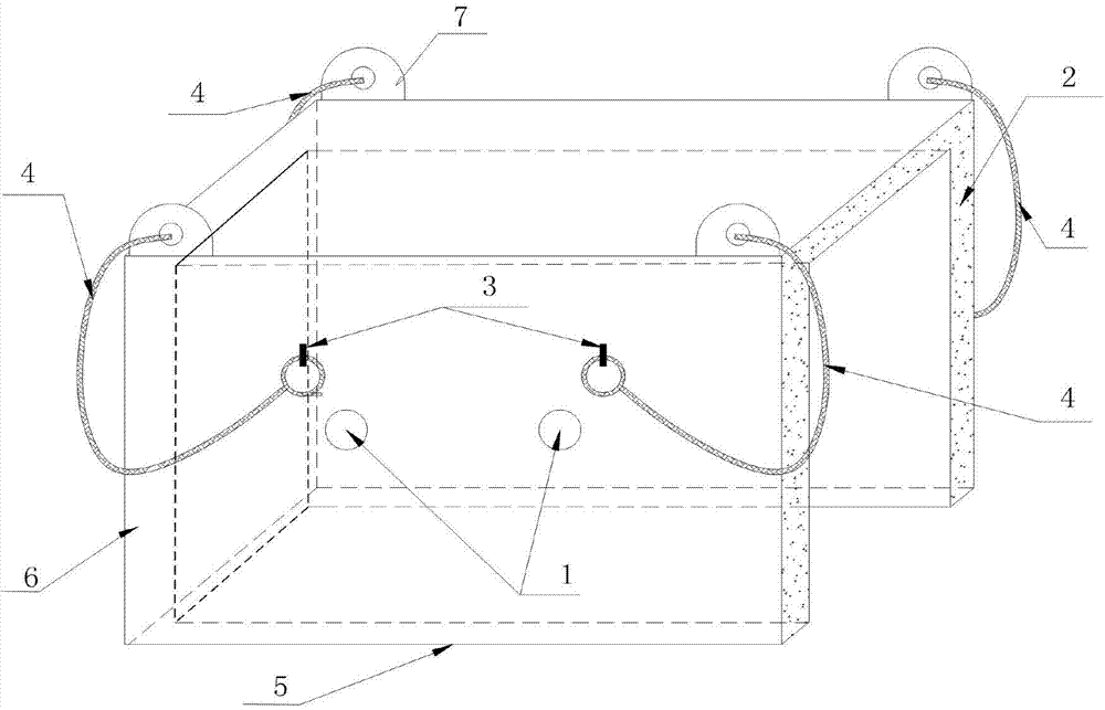
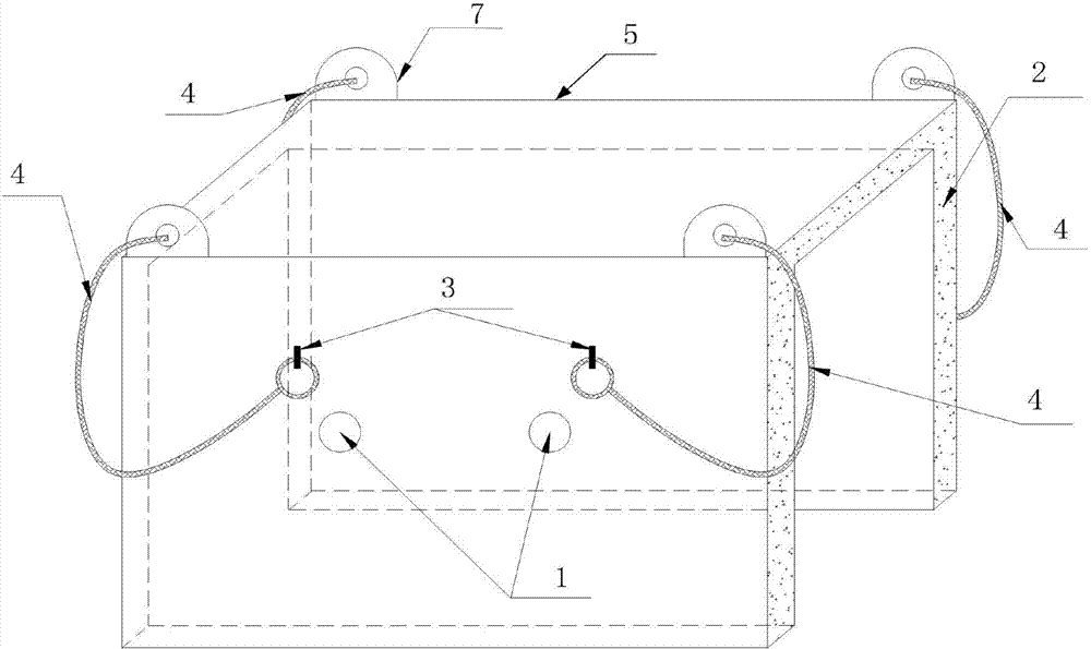
[0042] The production of wide and thick plate steel for wind power that requires Class I flaw detection is Q345BZ15. After the steel plate is rolled, it will be stacked immediately in a red hot state, and the end box and the middle box will be used to cover the stack. After 20 hours The temperature of the steel plate is slowly lowered to below the ideal temperature of 150°C. The results of metallographic experiments after sampling the steel plate show that there are no white spot defects in the internal structure of the steel plate, and at the same time, the thermal stress and structural stress caused by the recooling process of the hot steel plate are effectively avoided. The cracks meet the requirements of Class I flaw detection.

Embodiment example 2

[0044]Wide and thick plate production line, the end box and the middle box are used to cover the stack during production, the actual temperature of the steel plate is detected in real time through the temperature measuring hole during the slow cooling process of the steel plate, and the reasonable timing of opening the slow cooling device to lift out the steel plate is accurately grasped ( The ideal temperature is below 150°C), which ensures the slow cooling effect of the steel plate. The pass rate of flaw detection of the steel plate has risen from 91% per quarter to 99.5%, reaching the domestic first-class level, thereby achieving the purpose of improving the product yield, resulting in great Considerable economic benefits.


PUM


Abstract

The invention discloses a slow cooling device for steel plates. The slow cooling device for steel plates comprises a temperature measuring hole, thermal insulation material, a hook, a steel wire rope, a shell and a lifting lug. The shell is of a box-type structure and comprises three side faces, the thermal insulation material is filled into the interlayer of the shell, and the lifting lug is fixed to the top of the shell; one end portion of the steel wire rope penetrates in the lifting lug, and a hook is arranged on the other end portion of the steel wire rope; the temperature measuring hole is formed in one side face of the shell, and a temperature measuring hole choke plug is installed on the temperature measuring hole. The invention further discloses a slow cooling method for steel plates. With the slow cooling device and method for steel plates, hot steel plates can undergo thermal insulation and be slowly cooled after being rolled and taken off the line timely, the slow cooling degree of the steel plates is controlled, the reasonable time for opening the slowing cooling device to lift out the steel plates is accurately judged, and thus the slow cooling effect on the steel plates can be guaranteed.

Description

technical field [0001] The invention relates to a steel rolling equipment, in particular to a steel plate slow cooling device and a slow cooling method thereof. Background technique [0002] In the production of wide and thick plates, the hot steel plate usually needs to be kept warm and slowly cooled after rolling. By controlling the cooling rate, the white spot defects inside the steel plate can be eliminated, and at the same time, the thermal stress caused by the hot steel plate during the cooling process can be avoided. Cracks caused by tissue stress. If the hot steel plate does not have reasonable heat preservation and slow cooling, it will obviously affect the flaw detection pass rate of the steel plate and various indicators such as tissue performance. Especially in the winter in the north, the temperature of the factory building usually falls below 0 degrees, and there will be disadvantages such as too fast cooling of the hot steel plate. Therefore, effectively con...

Claims


Application Information

Patent Timeline
Patent Type & Authority Applications(China)
IPC IPC(8): B21B45/02
Inventor 王皓张大治丁晓志高军关胜王爱兰
Owner INNER MONGOLIA BAOTOU STEEL UNION
Why Eureka
Try Eureka