
Multi-channel separation function signal generator and signal generating method

A function signal, multi-channel technology, applied in the field of multi-channel isolated function signal generators, can solve the problems of bulky, inconvenient operation, large waveform distortion, etc., to achieve the effect of wide application fields and improved technical indicators

Inactive Publication Date: 2014-02-26
HARBIN UNIV OF SCI & TECH
View PDF3 Cites 11 Cited by
  • Summary
  • Abstract
  • Description
  • Claims
  • Application Information

AI Technical Summary

Problems solved by technology

Since the time base of each multiple function generators is different, the parameter settings are not synchronized, which will also cause the time accumulation distortion of the series waveform signal, the longer the time, the greater the waveform distortion
Moreover, multiple function generators work at the same time, which is bulky and inconvenient to operate.

Method used


Image

  • Multi-channel separation function signal generator and signal generating method
  • Multi-channel separation function signal generator and signal generating method
  • Multi-channel separation function signal generator and signal generating method

Examples


Embodiment 1

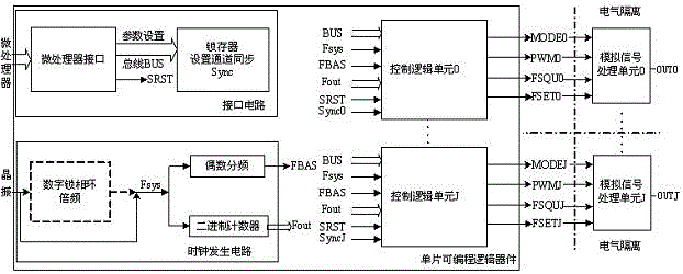
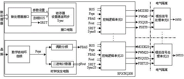
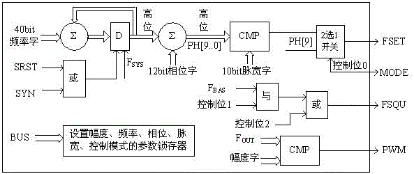
[0031] to combine figure 2 , which is the first preferred embodiment described in the present invention. figure 2 It is a block diagram of the 24-channel isolation function signal generator, image 3 for figure 2 The block diagram of the control unit shown in the control, Figure 4 for figure 2 The schematic block diagram of the analog unit shown, the working principle of each block diagram and the various application modes of the channel signals can be seen from the relevant discussion in the content of the invention above.

[0032] figure 2 The programmable logic device in the system adopts FPGA device EP2C8Q208; the external crystal oscillator clock frequency is 40MHz, the system clock Fsys is 280MHz after frequency multiplication by the phase-locked loop, and the base frequency clock FBAS is 140kHz.

[0033] exist image 3 In the shown logic control unit, the amplitude word is 16bit, the frequency word is 40Bit, the phase word is 12Bit, and the pulse width word ...

Embodiment 2

[0036] to combine Figure 5 , is the second preferred implementation mode of the present invention, and its working principle is the same as that of the first implementation mode, except that the parameters of components used and technical indicators of function signals are different.

[0037] exist Figure 5 Among them, the programmable logic device adopts CPKD device EPM570T100; Fsys is an external crystal oscillator frequency of 50MHz, and Fsys is a 25kHz base frequency clock FBAS divided by an even number.

[0038] Figure 5 In the shown control logic unit, the amplitude word is 16bit, the frequency word is 36Bit, the phase word is 12Bit, and the pulse width word is 10Bit. The amplitude resolution is 0.01%, the frequency of sinusoidal signal and pulse signal can reach 20kHz, the frequency resolution is 1mHz, the phase resolution is 0.1 degree, and the pulse width resolution is 0.1%.

[0039] exist Figure 5 Among them, the positive and negative 15V isolated power suppl...


PUM


Abstract

The invention provides a multi-channel separation function signal generator and a signal generating method. The multi-channel separation function signal generator comprises a single-chip programmable logic device and an analog unit, wherein an interface circuit, a clock generating circuit and logic control units are arranged in the programmable logic device in an embedded mode. According to the multi-channel separation function signal generator and the signal generating method, separation function signals of several or dozens of channels can be generated directly, each channel function signal has a direct current pattern or a sine pattern or a pulse pattern, the amplitude, the frequency, the phase position and the pulse width parameter of the signals of each channel can be set independently, and the amplitude reaches up to 20V.

Description

(1) Technical field [0001] The invention relates to a multi-channel isolation function signal generator, in particular to a multi-channel function signal generator that requires channel isolation, synchronization, multi-signal superposition, and large signal voltage variation range. (2) Background technology [0002] The function signal generator is a kind of signal generator, because it can generate sine waves with different amplitudes, different frequencies, and different phases, it is usually used as an excitation source in scientific research and equipment testing in many fields. For excitation signal sources in non-communication fields, the signal frequency band does not need to be very high. In some occasions, it is necessary to provide several channels of electrically isolated waveform signals as the excitation of different electrical equipment components, and sometimes these electrically isolated multi-channel signals are required to maintain a certain phase relation...

Claims


Application Information

Patent Timeline
Patent Type & Authority Applications(China)
IPC IPC(8): H03K3/02
Inventor 童子权任丽军于晓洋姜月明马艳艳熊浩东
Owner HARBIN UNIV OF SCI & TECH
Learn More