
Multi-channel sinusoidal signal generator and method for generating multi-channel sinusoidal signals

A sinusoidal signal, multi-channel technology, applied in electrical components and other directions, can solve the problems of jitter, low frequency of sinusoidal signals, affecting waveform quality, etc., to achieve the effect of low device cost, easy channel number, and low hardware cost

Inactive Publication Date: 2014-02-26
HARBIN UNIV OF SCI & TECH
View PDF1 Cites 15 Cited by
  • Summary
  • Abstract
  • Description
  • Claims
  • Application Information

AI Technical Summary

Problems solved by technology

If the SPWM signal is directly generated by digital logic, there will be three problems: first, the frequency of the triangle wave generated by digital logic cannot be too high, which directly determines that the frequency of the sinusoidal signal is relatively low. The frequency of the sine signal is lower; second, the state of the SPWM signal will change multiple times within a sine wave cycle, resulting in jitter. When the amplitude is small, the jitter will seriously affect the waveform quality; third, the SPWM signal needs to use a sine wave data, it needs to occupy memory resources, which in turn severely restricts the increase in the number of sinusoidal signal channels
[0005] To sum up, the existing multi-channel signal generation methods and implementation technologies cannot directly generate signals with more than ten channels. When the number of channels increases, multiple programmable logic devices need to work in parallel, which will cause output signals due to different sources of clocks. and the problem of not being able to actually sync

Method used


Image

  • Multi-channel sinusoidal signal generator and method for generating multi-channel sinusoidal signals
  • Multi-channel sinusoidal signal generator and method for generating multi-channel sinusoidal signals
  • Multi-channel sinusoidal signal generator and method for generating multi-channel sinusoidal signals

Examples


Embodiment 1

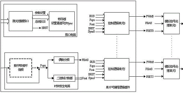
[0039] to combine image 3 , The 56-channel sinusoidal signal generating circuit of the present invention is composed of a single-chip FPGA device EP2C8Q208 and 56 completely identical analog signal conversion units. figure 2 The FPGA in it has built-in interface circuit, clock system generating circuit, and 56 control logic units with the same structure. The frequency of the external crystal oscillator is 40MHz, and the frequency multiplied by the digital phase-locked loop is 280MHz system clock Fsys. Driver requirements. Its working principle has been discussed in detail in the summary of the invention.

[0040] Figure 4 for image 3 The functional block diagram of the control logic unit in , and its working principle has been discussed in detail in the summary of the invention. Each control logic unit generates the amplitude control signal PWM and the phase frequency control signal FSET. The microprocessor sets the 16Bit amplitude word, 40Bit frequency word, and 12Bi...

Embodiment 2

[0043] to combine Figure 6 , The 120-channel sinusoidal signal generating circuit of the present invention is composed of a single-chip FPGA device EP2C20F484 and 120 identical analog signal conversion units. Figure 5 The FPGA in it has built-in interface circuit, clock system generation circuit, and 120 control logic units with the same structure. After FBAS buffers, it outputs through multiple pins of FPGA to meet the driving requirements of 120 channels. The functional indicators of each control logic unit and analog conversion unit are consistent with those of the first embodiment.

Embodiment 3

[0045] to combine Figure 7 , The 10-channel sinusoidal signal generating circuit of the present invention is composed of a single-chip CPLD device EPM1270T144 and 10 identical analog signal conversion units.

[0046] Figure 7 The CPLD has built-in interface circuit, clock generation circuit, and 10 control logic units with the same structure. 50MHz external crystal oscillator frequency direct system clock Fsys, without using digital phase-locked loop; Fsys is the fundamental frequency square wave FBAS after 2048 frequency division. Each control logic unit generates an amplitude control signal PWM and a phase frequency control signal FSET. The microprocessor sets the parameters of each channel as follows: 16Bit amplitude word, 36Bit frequency word, 12Bit phase word, the normal operating frequency of the phase frequency control signal FSET is variable within the range of 20kHz based on the FBAS frequency, and the sinusoidal signal frequency band generated by each channel is ...


PUM


Abstract

The invention discloses a multi-channel sinusoidal signal generator and a method for generating multi-channel sinusoidal signals. By the adoption of the multi-channel sinusoidal signal generator and the method for generating the multi-channel sinusoidal signals, the sinusoidal signals of tens of or hundreds of channels can be directly generated, and the amplitude, the frequency, and the initial phase of each signal can be digitally set; synchronization of the signals of all channels or signals of a plurality of channels can be achieved, and phase difference can be set between every two same-frequency signals. A waveform generation circuit is composed of a single programmable logic device and multiple analog units. Each analog unit is controlled by an amplitude control signal, a phase frequency control signal and a public fundamental frequency square signal. At least 2N+1 control lines, for driving the N channel analog units, of the programmable logic device are arranged. According to the multi-channel sinusoidal signal generator, a storage, a DAC and an analog multiplier are not applied to the waveform generation circuit, and only one programmable logic device, N analog multi-channel switches, N four-operational-amplifiers and N dual-operation-amplifiers are adopted, so that the hardware cost is low, and an analog circuit is simple. The multi-channel sinusoidal signal generator and the method for generating the multi-channel sinusoidal signals are suitable for application occasions requiring one or more characteristics such as a large number of channels, channel synchronization, and channel isolation.

Description

(1) Technical field [0001] The invention relates to a multi-channel sinusoidal signal generator, in particular to a multi-channel sinusoidal signal generator with features as high as tens or even hundreds, requiring synchronization and the like. (2) Background technology [0002] The sinusoidal signal generator is the most basic signal generator. Because it can generate sinusoidal signals with variable amplitude, frequency and phase, it is usually used as an excitation source in electronic test systems and is widely used in power system simulation, sonar excitation, In applications such as medical diagnosis, it is necessary to apply multiple sinusoidal signals, and sometimes it is necessary to maintain a synchronous relationship and a certain phase relationship between the signals, which requires the use of a multi-channel sinusoidal signal generator. [0003] The existing multi-channel function / arbitrary waveform generator can be used as a multi-channel sinusoidal signal ge...

Claims


Application Information

Patent Timeline
Patent Type & Authority Applications(China)
IPC IPC(8): H03B28/00
Inventor 童子权于晓洋任丽军于海涛汪俊杰姜月明
Owner HARBIN UNIV OF SCI & TECH
Learn More