Charging and discharging circuit with automatic protecting function

A charging and discharging circuit and automatic protection technology, applied in battery circuit devices, circuit devices, current collectors, etc., can solve the problems of high cost and complicated circuit, and achieve the effect of reducing the area, simple circuit design and cost saving.

Active Publication Date: 2014-02-26
钰泰半导体股份有限公司
View PDF2 Cites 11 Cited by
  • Summary
  • Abstract
  • Description
  • Claims
  • Application Information

AI Technical Summary

Problems solved by technology

It can be seen that in the prior art, in order to realize the charging, discharging control and automatic protection functions of the mobile power supply, at least a fuse 103, back-to-back N-type field effect transistors 112 and three independent integrated circuit chips-the charger 101, boost converter 105 and battery protection chip 111, resulting in complex circuit and high cost

Method used


Image

  • Charging and discharging circuit with automatic protecting function
  • Charging and discharging circuit with automatic protecting function
  • Charging and discharging circuit with automatic protecting function

Examples


Embodiment Construction

[0036] Below, according to the accompanying drawings, preferred embodiments of the present invention are given and described in detail, so that the functions and features of the present invention can be better understood.

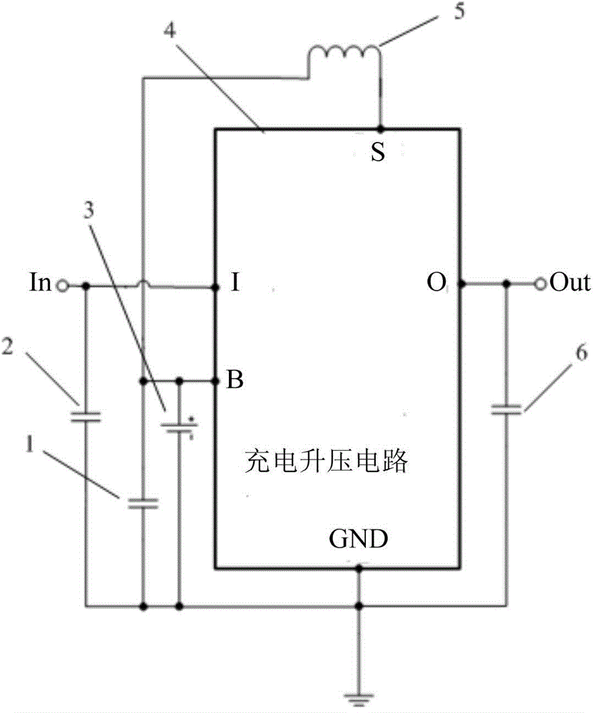
[0037] figure 2 and image 3 An embodiment of the charging and discharging circuit of the present invention is shown, as shown in the figure, the charging and discharging circuit includes a power input terminal In, a power output terminal Out, a battery 3, a battery composed of a charging module and a boost module Charging and boosting circuit 4, its circuit structure is described in detail below:

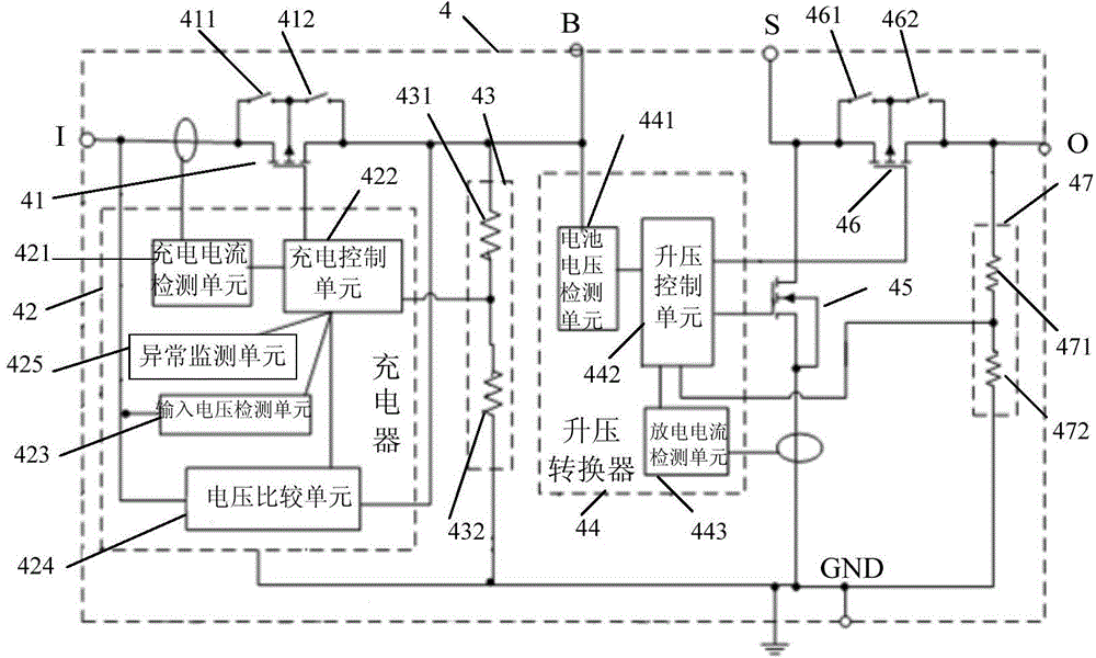
[0038] like image 3As shown, the charging module in this embodiment includes a charger 42 connected between the power input terminal (node ​​I) and the positive pole (node ​​B) of the battery 3 and connected to the ground GND, and the charger 42 includes a charger 42 for A charging current detection unit 421 for measuring the current at the input terminal o...


PUM


Abstract

The invention provides a charging and discharging circuit with an automatic protecting function. The charging and discharging circuit comprises a power source input end, a power source output end, a battery, a charging module and a voltage boost module, wherein the charging module comprises a charger, a battery voltage feedback unit and a first switch unit, the charger comprises a charging current detecting unit, an input voltage detecting unit, a voltage comparison module and a charging control unit, and the first switch unit is connected between the power source input end and the battery; the voltage boost module comprises a voltage boost converter, an output voltage feedback unit, a power switch tube and a second switch unit, and the voltage boost converter comprises a battery voltage detecting unit, a discharging current detecting unit and a voltage boost control unit. The charging and discharging circuit achieves the automatic protecting function and meanwhile can reduce the number of components, and therefore the overall area of the circuit is reduced, cost is saved, the complexity of the circuit is reduced, and the reliability of the circuit is improved.

Description

technical field [0001] The invention relates to the field of integrated circuits, in particular to a charging and discharging circuit with an automatic protection function. Background technique [0002] In order to realize the charging, discharging and protection functions of the mobile power supply, the traditional circuit generally consists of three parts, such as figure 1 As shown, it includes: a charging module composed of a charger 101 and a P-type field effect transistor 102 with a switchable substrate, and a charging module composed of a fuse 103, a battery protection chip 111 and back-to-back N-type field effect transistors 112. A battery protection module for protecting the battery 104 , and a boost module composed of a boost converter 105 , an inductor 106 , an N-type field effect transistor 107 , a rectifier diode 108 , and feedback resistors 109 and 110 . [0003] The following takes the battery 104 as a lithium battery (but not limited to a lithium battery) as ...

Claims


Application Information

Patent Timeline
IPC IPC(8): H02J7/00H02J7/02
Inventor 甘戈
Owner 钰泰半导体股份有限公司
Why Eureka
Try Eureka