
A t-shaped interleaved double-gate slow-wave device

A device and slow-wave technology, applied in the field of vacuum electronics, can solve the problems of injection-wave interaction efficiency, low output power, poor device output power and gain, poor dispersion characteristics, etc., to enhance the local characteristics of the electric field and increase the output Power and efficiency, and the effect of high coupling impedance

Active Publication Date: 2015-12-30
UNIV OF ELECTRONICS SCI & TECH OF CHINA
View PDF3 Cites 0 Cited by
  • Summary
  • Abstract
  • Description
  • Claims
  • Application Information

AI Technical Summary

Problems solved by technology

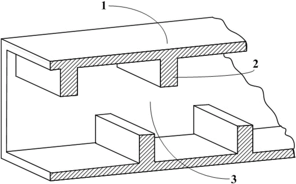
However, due to the weak electric field in the longitudinal propagation direction (parallel to the strip-shaped electron beam) of this type of rectangular interleaved double-gate slow-wave device, the coupling impedance in the high-frequency characteristics of the device is low and the dispersion characteristics are poor, which leads to the beam-wave interaction efficiency. , low output power, poor overall output power and gain of the device, etc.

Method used


Image

  • A t-shaped interleaved double-gate slow-wave device
  • A t-shaped interleaved double-gate slow-wave device
  • A t-shaped interleaved double-gate slow-wave device

Examples


Embodiment Construction

[0014] This implementation mode takes a T-shaped interleaved double-gate slow-wave device with an operating frequency range of 138-155 GHz as an example.

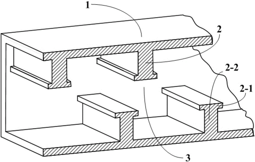
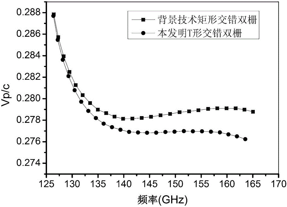
[0015] Set the specific dimensions as follows: the end face (cross-section) width×height of the T-shaped staggered double-gate slow-wave device is 1.21mm×1.07mm, the period is 0.75mm, the height of the electron injection channel is 0.21mm, and the height of the T-shaped grid is 0.43mm, the height of the grid cap is 0.05mm, the thickness of the rectangular body is 0.17mm, and the thickness of the grid cap is 0.20mm; the width of the grid cap of the rectangular interlaced double-gate slow-wave device is 0.17mm, and other parameters are the same as those of the T-shaped The staggered double gates are consistent; two kinds of staggered double gate slow-wave devices are obtained, and then the above slow-wave devices are simulated by using 3D electromagnetic simulation software, and the dispersion curve is obtained as image 3 , ...


PUM


Abstract

The invention provides a T-shape staggered double-grid slow-wave device, belongs to the vacuum electronic technology field and relates to the slow-wave device which works in a millimeter wave and terahertz band travelling wave tube. The device comprises a shell and grid bodies arranged on an upper top surface and a lower bottom surface of an inner cavity. Each grid body arranged on the upper top surface and the lower bottom surface of the inner cavity is a ''T''-shape grid body, wherein a lower portion of the grid body is a rectangular body and a top portion is provided with a flat grid cover. The two adjacent ''T''-shape grid are dislocated for half a period along an axis direction. Each ''T''-shape grid body of the upper top surface and each ''T''-shape grid body of the lower bottom surface are arranged in a staggered mode with an equal distance. There is a half of a period length difference between an upper row of the ''T''-shape grids and a lower row of the''T''-shape grids. By using the device of the invention, there are the following advantages that coupling impedance is high and a dispersion characteristic is excellent; the whole device is miniaturized relatively and so on. The device is especially suitable for a terahertz band-shape electronic injection device. High output power and efficiency are possessed.

Description

technical field [0001] The invention belongs to the technical field of vacuum electronics, and relates to a slow-wave device working in millimeter wave and terahertz wave band traveling wave tubes. Background technique [0002] Terahertz technology is one of the most promising technologies today, and it has broad application prospects in the fields of communication and imaging. However, due to the lack of suitable terahertz power sources, the development of the electromagnetic spectrum in the terahertz band is still blank. Vacuum electronics have great potential to realize high-power terahertz sources. Traveling wave tubes are the most important microwave and millimeter wave amplifiers in the field of vacuum electronics. They have the characteristics of high power, high efficiency, high gain, broadband and long life. They are widely used in radar, guidance, satellite communication, and microwave remote sensing. , radiation measurement and other fields, its performance dire...

Claims


Application Information

Patent Timeline
Patent Type & Authority Patents(China)
IPC IPC(8): H01J23/42
Inventor 段兆云王彦帅唐涛唐先锋宫玉彬
Owner UNIV OF ELECTRONICS SCI & TECH OF CHINA
Learn More