
Method and device for electrolytic machining of massive array tiny pits through wedge-shaped runner

A wedge-shaped flow, massive technology, used in electric machining equipment, electrochemical machining equipment, machining electrodes, etc., can solve the problem of stray corrosion of pits in the liquid outlet area, good pit quality in the liquid inlet area, and poor uniformity of small pits, etc. problems, to achieve the effect of improving uniformity and machining accuracy, reducing stray corrosion, and high bonding strength

Active Publication Date: 2014-02-26
NANJING UNIV OF AERONAUTICS & ASTRONAUTICS
View PDF4 Cites 16 Cited by
  • Summary
  • Abstract
  • Description
  • Claims
  • Application Information

AI Technical Summary

Problems solved by technology

[0006] The present invention proposes a method and device for electrolytically processing a massive array of micro-pits in a wedge-shaped flow channel to solve the problem of poor uniformity of micro-pits along the direction of the flow channel in the processing of a large number of micro-pits arrays in the prior art, and the liquid inlet area The quality of the pits is good, and the technical problem of serious stray corrosion of the pits in the liquid outlet area

Method used


Image

  • Method and device for electrolytic machining of massive array tiny pits through wedge-shaped runner
  • Method and device for electrolytic machining of massive array tiny pits through wedge-shaped runner
  • Method and device for electrolytic machining of massive array tiny pits through wedge-shaped runner

Examples


Embodiment Construction

[0029] The present invention will be described in detail below in conjunction with the accompanying drawings.

[0030] The method for electrolytically machining a large number of arrays of tiny pits in a wedge-shaped flow channel of the present invention specifically includes the following steps:

[0031] 1) Utilize an atmospheric pressure plasma surface treatment machine to process the surface of the mask plate 3 having a group of holes and a consistent structure of the group of holes to improve its bonding strength with the metal;

[0032] 2) closely attaching the mask plate 3 to the surface of the anode of the workpiece 4;

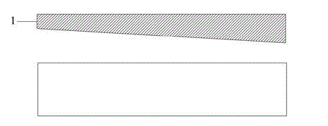
[0033] 3) Fixing the cathode of the wedge-shaped tool 1 above the mask plate 3 to form a wedge-shaped flow channel 2 between the mask plate 3 and the mask plate 3;

[0034] 4) Connect the anode of the workpiece 4 and the cathode of the wedge tool 1 to the positive and negative poles of the power supply 6 respectively;

[0035] 5) The electrolyte solut...


PUM


Abstract

The invention discloses a method and a device for electrolytic machining of massive array tiny pits through a wedge-shaped runner, and belongs to the technical field of electrolytic machining. The method includes processing the surface of a mask plate to enable the surface to fit with the surface of a workpiece anode; fixing a wedge-shaped tool cathode above the mask plate to enable the wedge-shaped runner to be formed between the wedge-shaped tool cathode and the mask plate; connecting the workpiece anode and the wedge-shaped tool cathode with an anode and a cathode of a power source respectively; feeding an electrolyte into the wedge-shaped runner, wherein the electrolyte reaches the surface of the workpiece anode through penetrating group holes in the mask plate; switching on the power source for electrolytic machining. The runner is arranged to be wedge-shaped, so that electric field intensity and electrolyte flowing speed are enabled to be progressively increased along the direction of the runner, both corrosion strength and speed of a workpiece are enabled to tend to be uniform, and uniformity and machining accuracy of electrolytic machining are improved. A PDMS (polydimethylsiloxane) template is taken as the mask plate, bonding strength of the mask plate and the workpiece anode can be guaranteed, stray corrosion, of the electrolyte, to places around a machining area can be effectively reduced, and locality and uniformity of electrolytic machining can be improved.

Description

technical field [0001] The invention relates to a method and a device for electrolytically machining a large number of micro-pits in a wedge-shaped flow channel, and belongs to the technical field of electrolytic machining. Background technique [0002] There are all kinds of friction pairs in general mechanical device systems. The tribological behavior of these friction pairs not only affects the working performance and operating efficiency of the mechanical system, but is even the main factor leading to its failure. According to survey statistics, 30% of the energy in industrialized countries is consumed by mechanical friction. At the same time, about 80% of parts failure is caused by various forms of mechanical friction and wear. Therefore, controlling friction, reducing wear and improving lubricating performance have become important means to save energy and raw materials. [0003] Israel's I. Etsion et al. are the earliest scholars in the world who used laser processin...

Claims


Application Information

Patent Timeline
IPC IPC(8): B23H3/00B23H3/04B23H11/00
Inventor 陈晓磊李寒松曲宁松
Owner NANJING UNIV OF AERONAUTICS & ASTRONAUTICS
Learn More