Indoor heat storage solar cooker
A solar cooker and heat storage technology, which is applied in the application field of solar cookers, can solve the problems of boiling water, cooking is affected, cannot be fully utilized, and the use environment is not good, and achieves the effects of improving the use environment, low cost, and easy management
- Summary
- Abstract
- Description
- Claims
- Application Information
AI Technical Summary
Problems solved by technology
Method used
Image
Examples
specific Embodiment approach 1
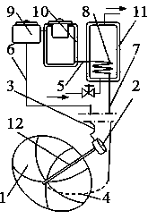
[0028] exist figure 1 In the shown embodiment, when the height of the heat collector 2 is lower than the heating stove 9, the heat storage and heat preservation stove 10, and the heat preservation water tank 11:
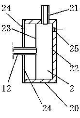
[0029] The upper end of the heat preservation pipe 12 passes through the reflector 1 and communicates airtightly with the heat collector 2, and fixes the heat collector 2 on the focal point or focal line of the reflector 1; the receiving surface of the heat collector 2 is larger than the focal point of the reflector 1 spot, and its receiving surface is similar to the focal spot shape of the reflector 1;
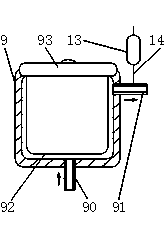
[0030] The outlet end 21 of the heat collector 2 is airtightly connected with one end of the heat preservation delivery hose 3, the other end of the heat preservation delivery hose 3 is airtightly connected with the heat preservation delivery pipe 6, and the other end of the heat preservation delivery pipe 6 is airtight with the inlet pipe 90 of the heating ...
specific Embodiment approach 2
[0038] Such as Figure 5 with figure 1 , image 3 As shown, when the height of the heat collector 2 is higher than the heating stove 9, the heat storage and heat preservation stove 10, and the heat preservation water tank 11:
[0039] A pump 15 is connected between the outlet end of the heat exchange pipe 8 of the heat preservation water tank 11 and the heat preservation return pipe 7; The bottom of the tank 13 is in airtight communication, the top in the tank 13 is in communication with the outside of the tank 13, and the bottom of the tank 13 is higher than the height of the heat collector 2. which is image 3 The pipe 14 and tank 13 that are connected in should be connected in Figure 5 location shown. The temperature sensor 25 is pasted on the outer surface 22 of the heat collector 2. When the temperature is higher than the predetermined temperature, the electric control device starts the motor to drive the pump 15 to run. When the temperature is lower than the pr...
PUM
 Abstract
Description
Claims
Application Information
 - R&D Engineer
- R&D Manager
- IP Professional
- Industry Leading Data Capabilities
- Powerful AI technology
- Patent DNA Extraction
Browse by: Latest US Patents, China's latest patents, Technical Efficacy Thesaurus, Application Domain, Technology Topic, Popular Technical Reports.
© 2024 PatSnap. All rights reserved.Legal|Privacy policy|Modern Slavery Act Transparency Statement|Sitemap|About US| Contact US: help@patsnap.com


