
Numerical control plate shearing and stacking production line

A production line and stacking technology, applied in shearing devices, shearing machines, stacking of objects, etc., can solve problems such as the inability to separate waste from qualified workpieces, the inability to accurately control the size of the material plate, and the increase of operator labor intensity. , to achieve the effect of improving product qualification rate, precise size control, and labor saving

Active Publication Date: 2014-02-19
江苏麦斯铁机械有限公司
View PDF7 Cites 19 Cited by
  • Summary
  • Abstract
  • Description
  • Claims
  • Application Information

AI Technical Summary

Problems solved by technology

[0002] In the existing shearing machine, the shearing accuracy is controlled by the positioning of the back gauge, and the back gauge will lose its original accuracy during repeated positioning and collision, resulting in the inability to accurately control the size of the sheared material plate; The blanking of the technology is designed by sliding down the blanking plate fixed at the rear of the equipment and stacking the workpiece naturally. First, it is impossible to separate the waste from the qualified workpiece, and second, manual classification, picking, stacking, sorting and other follow-up are required. work, which not only increases the labor intensity of the operator, but also reduces work efficiency

Method used


Image

  • Numerical control plate shearing and stacking production line
  • Numerical control plate shearing and stacking production line
  • Numerical control plate shearing and stacking production line

Examples


Embodiment Construction

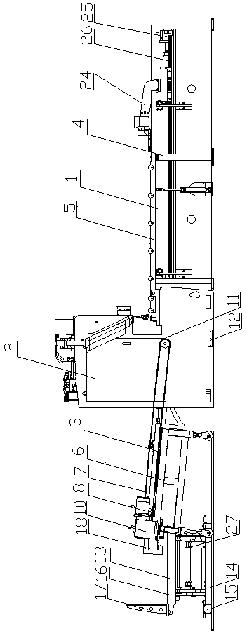
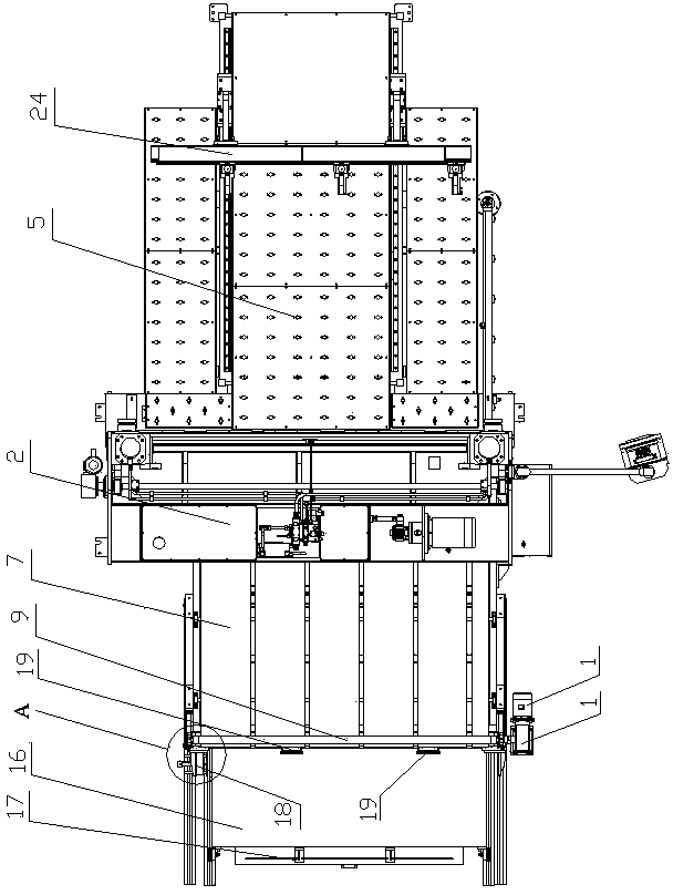
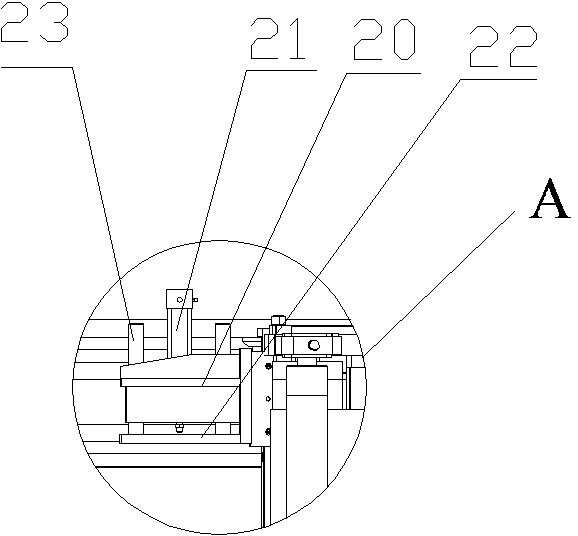
[0015] like figure 1 , 2 , 3, 4, and 5, the CNC shearing and palletizing production line includes a front feeding mechanism 1, a shearing machine host 2, a rear discharging mechanism 3, a front feeding mechanism 1, and a rear discharging mechanism 3 respectively. Cooperate with the front and rear ends of the shearing machine host 2; the front feeding mechanism 1 includes a bottom bracket 4, and a delivery platform 5 is arranged on the bottom bracket 4, and a feeding clamp 24 is arranged on the top of the delivery platform 5, and the front of the delivery platform 5 Servo motors 25 and ball screws 26 are respectively provided on both sides of the bottom bracket, and one end of each ball screw 26 is respectively connected to the output ends of two servo motors 25, and the other end of the ball screws 26 is connected to the feeding clamp respectively. 24 connection; the rear discharge mechanism 3 includes a bottom bracket 6, a conveyor belt 7 is set on the bottom bracket 6, a di...


PUM


Abstract

The invention provides a numerical control plate shearing and stacking production line, and belongs to the field of machinery. The numerical control plate shearing and stacking production line comprises a front feed mechanism, a main machine of a plate shearing machine and a rear discharge mechanism, wherein the front feed mechanism and the rear discharge mechanism are matched with and connected to the front end of the main machine of the plate shearing machine and the rear end of the main machine of the plate shearing machine respectively. The front feed mechanism comprises a bottom support, wherein a conveying platform is arranged on the bottom support, and a feeding clamp is matched above the conveying platform. The rear discharge mechanism comprises a bottom support, wherein a conveying belt is arranged on the bottom support, a discharge motor and a feed roller are arranged at the rear end of the bottom support, the discharge motor is in drive connection with the feed roller through a speed reducer, the feed roller is in matched transmission with the conveying belt, the discharge motor rotates forward and backward to drive the feed roller to conduct bidirectional rotation, and a material falling interval is arranged between the rear discharge mechanism and the main machine of the plate shearing machine. According to the numerical control plate shearing and stacking production line, disqualified materials do not need to be separated through manual work, and therefore the automation degree of equipment is greatly improved, the shearing accuracy is high, and the product percent of pass is high.

Description

technical field [0001] The invention belongs to the field of machinery, in particular to the field of manufacturing technology of a shearing machine production line. Background technique [0002] The cutting accuracy of the existing shearing machine is controlled by the positioning of the back gauge, and the back gauge will lose its original accuracy during repeated positioning and collision, resulting in the inability to accurately control the size of the sheared material plate; The technical blanking is designed by sliding down the blanking plate fixed at the rear of the equipment and stacking the workpieces naturally. First, the separation of waste and qualified workpieces cannot be achieved, and second, manual classification, picking, stacking, sorting, etc. are required for follow-up Work, this not only increases the labor intensity of the operator, but also low work efficiency. Contents of the invention [0003] In order to solve the above technical problems, the pr...

Claims


Application Information

Patent Timeline
IPC IPC(8): B23D15/06B23D33/02B65G47/256B65G57/03
Inventor 许华东
Owner 江苏麦斯铁机械有限公司
Learn More