


Quick Research
Generate reliable direction feasibility study reports for your R&D in just a few steps.

Technical Q&A
Discover and master advanced knowledge NOW. Basics, ideas, possibilities, all at once.

Find Solutions
As an expert in R&D theories, this can generate solutions to your technical problems instantly.

Evaluate Feasibility
Analyze your overall solution with one click, know your potential R&D risks in advance.

Monitor Landscape
Get weekly tech updates, stay abreast of the latest tech innovations and key insights.
Flue gas treating device capable of synchronously removing sulfur, saltpeter, mercury and dedusting and its method
A technology for desulfurization, denitration, mercury removal, and flue gas treatment, which is applied in the field of flue gas treatment of synchronous desulfurization, denitrification, mercury removal and dust removal, and flue gas treatment devices for synchronous desulfurization, denitration, mercury removal and dust removal, which can solve the problem of large volume, large initial investment, and operating costs. High-level problems, to achieve the effect of preventing dust clogging, preventing the decline of removal rate, and rapid desulfurization, denitrification and demercury
- Summary
- Abstract
- Description
- Claims
- Application Information
AI Technical Summary
Problems solved by technology
Method used
Image

Examples
Embodiment 1
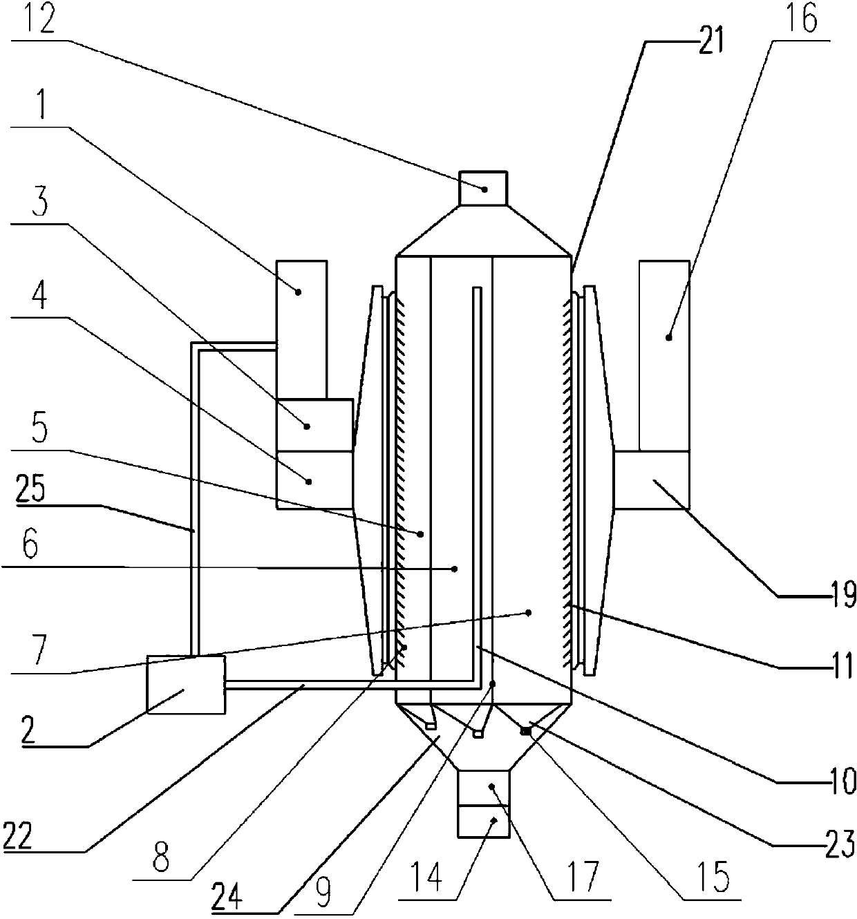
[0052] The flue gas treatment device of the synchronous desulfurization, denitrification, dedusting and dedusting of the present embodiment, such as figure 1 As shown, the reactor housing 21 is included, and the reactor housing 21 is provided with a flue gas inlet 4 for communicating with the intake flue 1 and a flue gas outlet 19 for communicating with the exhaust flue 16 The interior of the reactor housing 21 is longitudinally provided with two parallel porous partition devices 9, which divide the interior of the reactor housing 21 into a front chamber 5, a middle chamber 6, and a rear chamber in sequence along the flue gas flow direction. 7. The porous partition device 9 is a porous partition, and the aperture of the porous partition is 20mm; the front chamber 5, the middle chamber 6, and the rear chamber 7 are used to hold the medium-microporous activated carbon adsorbent. The volume ratio of the front chamber 5, the middle chamber 6 and the rear chamber 7 is 20:35:45.
...
Embodiment 2
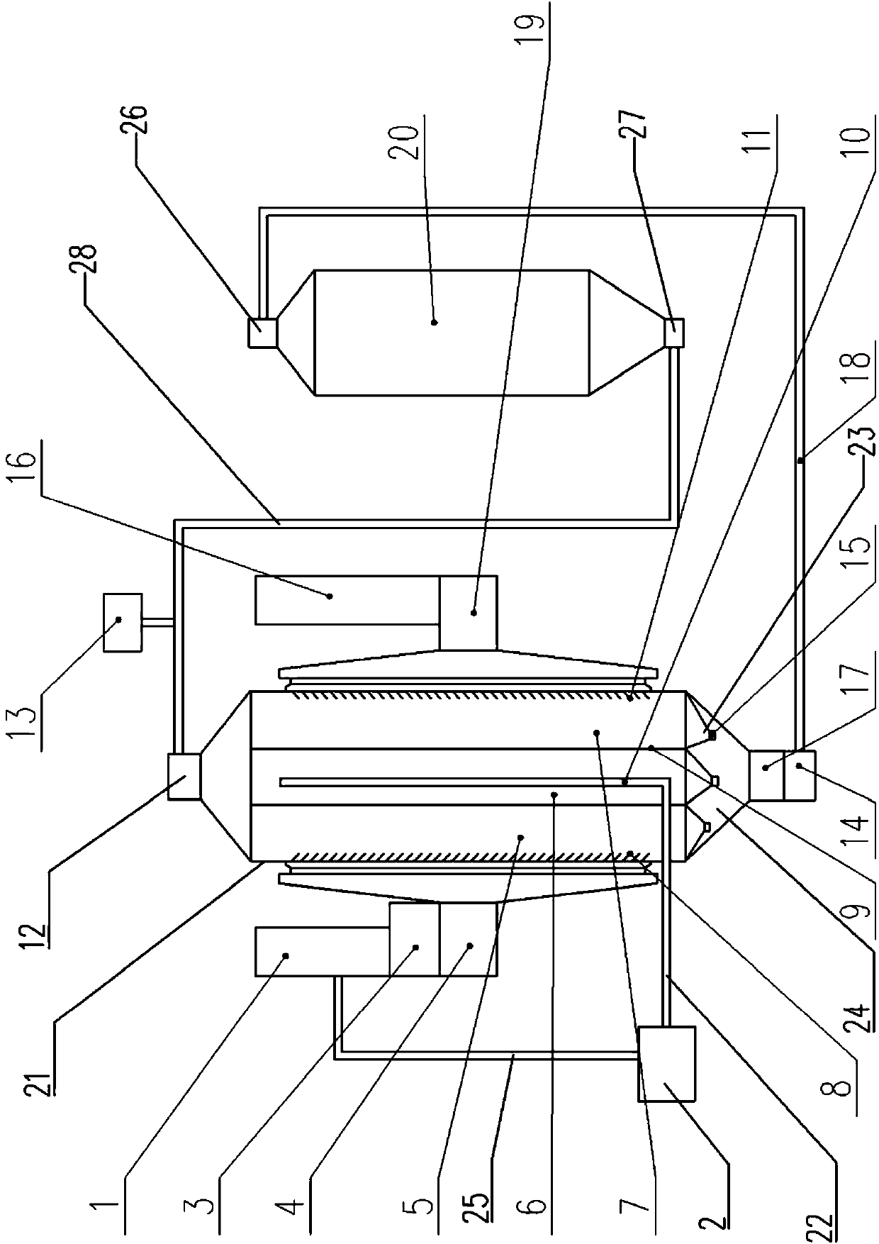
[0065] The flue gas treatment device of the synchronous desulfurization, denitrification, dedusting and dedusting of the present embodiment, such as figure 2 As shown, the difference from Example 1 is: the volume ratio of the front chamber 5, the middle chamber 6, and the rear chamber 7 is 33:33:33; it also includes an adsorbent regeneration device, and the adsorbent regeneration device is A high-temperature desorption tower 20; the high-temperature desorption tower 20 is provided with an adsorbent inlet 26 and an adsorbent outlet 27, and the adsorbent outlet 27 communicates with the feed port 12 of the reactor shell 21 through a regenerated material pipeline 28 , the adsorbent inlet 26 communicates with the saturated material outlet 17 of the reactor shell 21 through the saturated material pipeline 18, and the saturated material outlet 17 is provided with a rotary valve 14; the regenerated material pipeline 28 and the saturated material pipeline 18 There are transmission and...
Embodiment 3
[0076] The flue gas treatment device for synchronous desulfurization, denitrification, dedusting and dedusting in this embodiment is the same as that in Embodiment 2.
[0077] The flue gas treatment method for synchronous desulfurization, denitrification, mercury removal and dust removal of this embodiment comprises the following steps:
[0078] 1) Fill a total of 6,000t of microporous activated carbon evenly from the feed port to the front, middle, and rear chambers. The filling volume of each chamber is 1,200t in the front chamber, 2,100t in the middle chamber, and Indoor 2700t; the adsorbent flows downward due to gravity, adjust the discharge valve at the bottom of each chamber, so that the discharge speed of the front chamber is 60t / hour, the discharge speed of the middle chamber is 48t / hour, and the discharge speed of the rear chamber The speed is 30t / hour;
[0079] 2) After the flue gas to be treated is uniformly mixed with ammonia in the flue (the temperature of the fl...
PUM
| Property | Measurement | Unit |
|---|---|---|
| Specific surface area | aaaaa | aaaaa |
| Volume | aaaaa | aaaaa |
Abstract
Description
Claims
Application Information
 - R&D Engineer
- R&D Manager
- IP Professional
- Industry Leading Data Capabilities
- Powerful AI technology
- Patent DNA Extraction
Browse by: Latest US Patents, China's latest patents, Technical Efficacy Thesaurus, Application Domain, Technology Topic, Popular Technical Reports.
© 2024 PatSnap. All rights reserved.Legal|Privacy policy|Modern Slavery Act Transparency Statement|Sitemap|About US| Contact US: help@patsnap.com