Backlight module

A technology for backlight modules and light source components, which is applied in the directions of optics, light guides, light sources, etc., and can solve the problems of increasing the thickness of the backlight module 100

Inactive Publication Date: 2014-02-12
CORETRONIC (SUZHOU) CO LTD
View PDF7 Cites 3 Cited by
  • Summary
  • Abstract
  • Description
  • Claims
  • Application Information

AI Technical Summary

Problems solved by technology

like Figure 5 In the existing design, since the backplane 106 is arranged on the outermost side of the backlight module 100, the bottom 106a of the backplane located under the light guide plate 104 and the bottom reflector 110 will increase the overall thickness of the backlight module 100

Method used


Image

  • Backlight module
  • Backlight module
  • Backlight module

Examples


Embodiment Construction

[0050] The aforementioned and other technical contents, features and effects of the present invention will be clearly presented in the following detailed description of the embodiments with reference to the accompanying drawings. The directional terms mentioned in the following embodiments, such as: up, down, left, right, front or back, etc., are only referring to the directions of the drawings. Accordingly, the directional terms are used to illustrate and not to limit the invention.

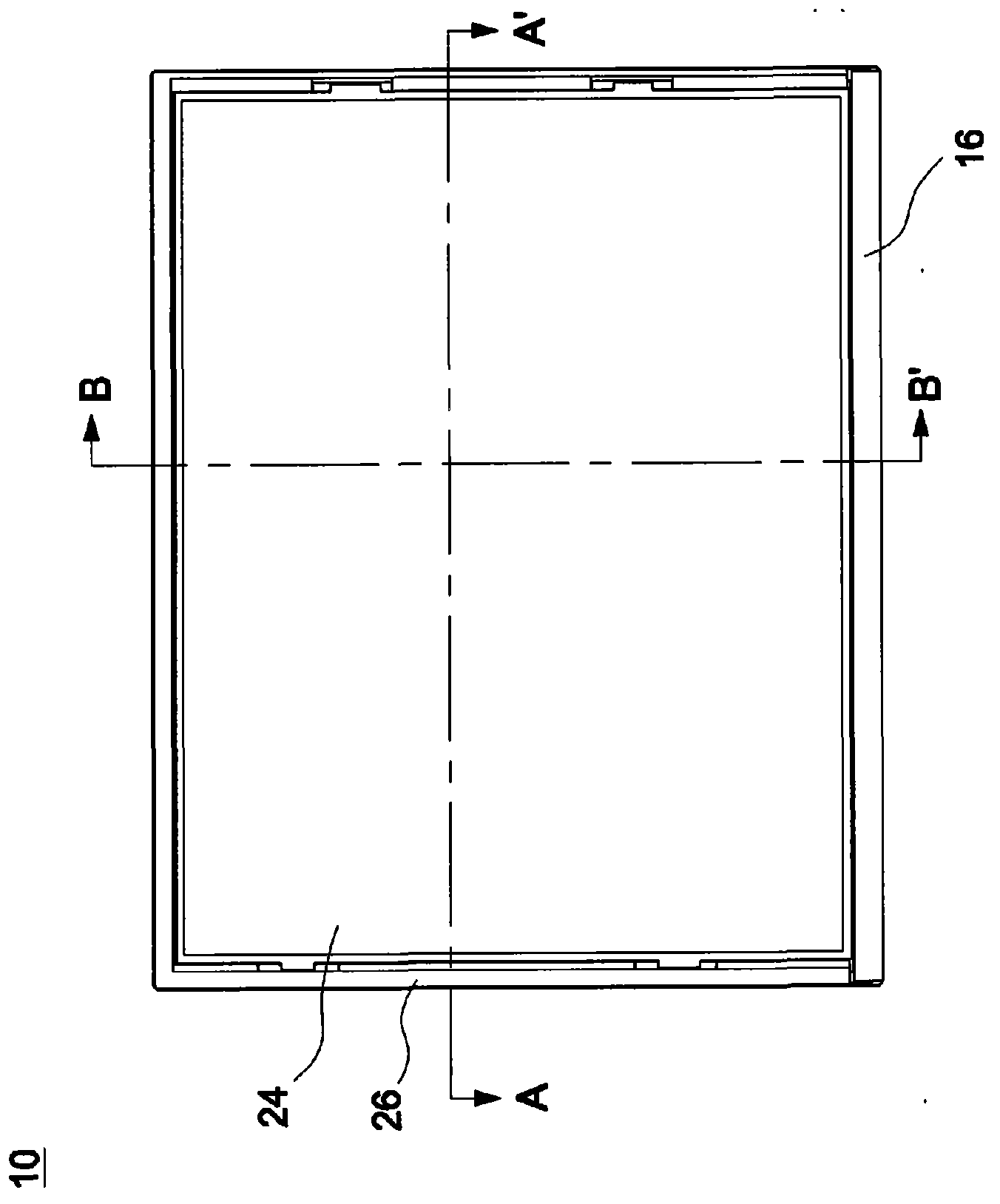
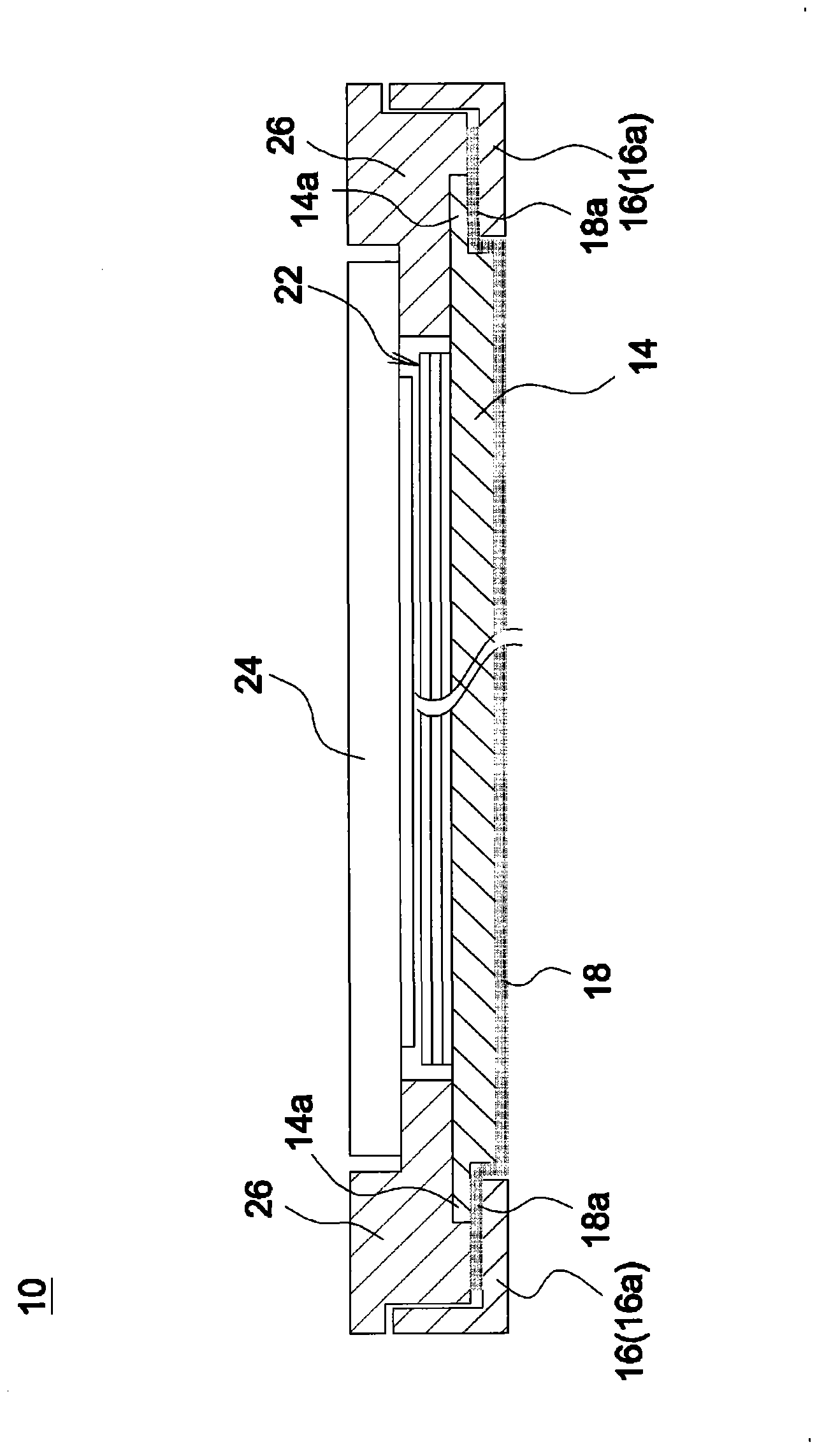
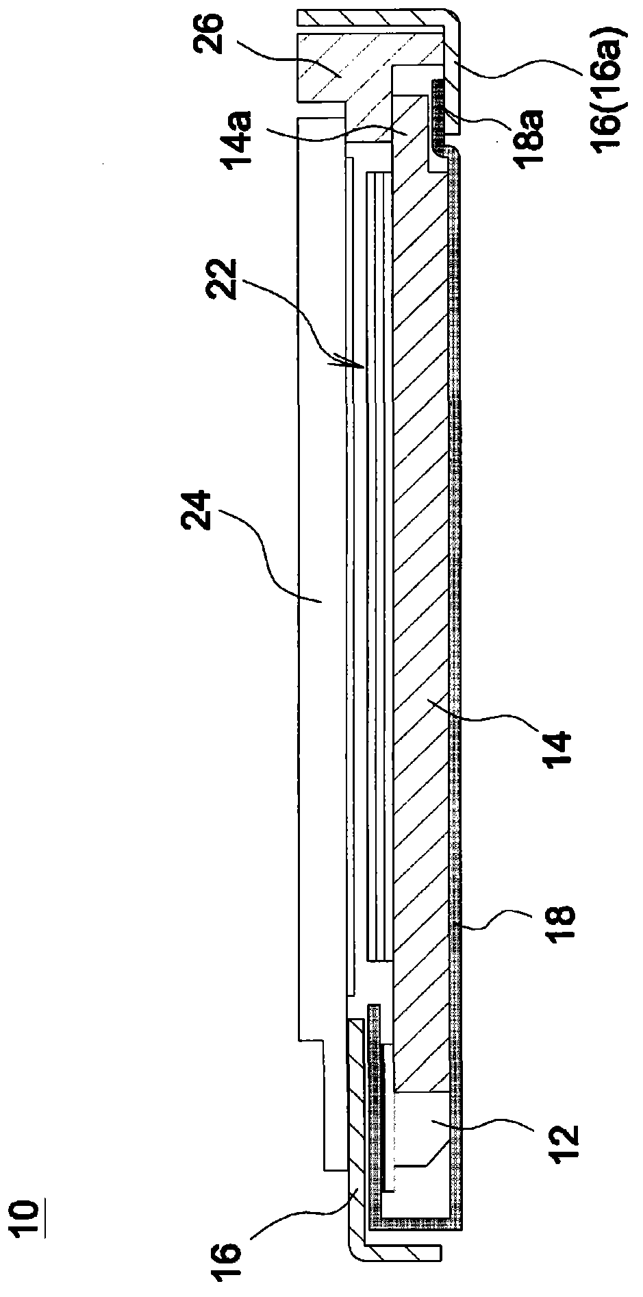
[0051] figure 1 is a schematic top view of a backlight module according to an embodiment of the present invention, Figure 2A for along figure 1 The enlarged cross-section of the A-A' line cut, and Figure 2B for along figure 1 The enlarged cross-section of the B-B' line cut. Please also refer to figure 1 , Figure 2A and Figure 2B , the backlight module 10 includes a light source assembly 12 , a light guide plate 14 and a back plate 16 . The light source assembly 12 can be, for ex...


PUM


Abstract

A backlight module comprises a light source assembly, a light guide plate and a back plate. The light guide plate comprises a plurality of sides. At least one side serves as an incident side close to the light source assembly. The light guide plate is used for guiding a beam emitted by the light source assembly. The light guide plate is in a stepped structure, and the stepped structure is formed on at least one side, except the incident side, of the light guide plate to form accommodating space. The back plate is embedded in the light guide plate, and at least part of the back plate is accommodated in the accommodating space formed by the stepped structure.

Description

technical field [0001] The invention relates to a backlight module. Background technique [0002] Figure 5 It is a schematic diagram of an existing backlight module. Such as Figure 5 As shown, the backlight module 100 includes a light source assembly 102 , a light guide plate 104 and a back plate 106 . The light guide plate 104 is disposed adjacent to the light source unit 102 and used to guide a light beam emitted by the light source unit 102 , and a plastic frame 108 limits the light guide plate 104 and the back plate 106 . Such as Figure 5 According to the existing design, since the backplane 106 is disposed on the outermost side of the backlight module 100 , the bottom 106 a of the backplane located below the light guide plate 104 and the bottom reflector 110 will increase the overall thickness of the backlight module 100 . [0003] US Patent Publication No. 20080291356 discloses a backlight module including a light guide plate, a first frame, a plurality of films, ...

Claims


Application Information

Patent Timeline
IPC IPC(8): F21S8/00F21V8/00F21V17/10G02F1/13357F21Y101/02F21Y115/10
Inventor 孟德宇王泽勇
Owner CORETRONIC (SUZHOU) CO LTD
Why Eureka
Try Eureka