Conducting building block

A technology of building blocks and conductive plates, applied in entertainment, sports accessories, toys, etc., can solve the problems of high consumption of process materials, inability to faithfully present luminous patterns, loss of power conduction, etc., and achieve the effect of saving a lot of money

Inactive Publication Date: 2017-12-01
LONGMEN GETMORE POLYURETHANE
View PDF4 Cites 0 Cited by
  • Summary
  • Abstract
  • Description
  • Claims
  • Application Information

AI Technical Summary

Problems solved by technology

In this solution, due to the arrangement of the protruding portion 91 of the electrical connector 90, it is impossible to reduce the thickness of the above-mentioned high-transmittance light-emitting building blocks, resulting in extremely high usage of process materials and increasing production costs.
[0004] In addition, once the connecting portion 92 of the electrical connector 90 breaks, other elastic pieces 93 connected in series with the connecting portion 92 may lose the function of power conduction, resulting in a plurality of highly transparent luminous building blocks that are stacked and combined with each other to only partially emit light. , so that the luminous pattern originally predetermined by the user cannot be faithfully presented
[0005] In addition, the shrapnel 93 away from the protruding portion 91 is likely to be damaged due to long-term stacking and combination of building blocks (that is, the shrapnel 93 of the high-transmittance light-emitting building block located below is in press contact with the circuit board 100 of the high-transparency light-emitting building block located above). The elastic fatigue of the remote connection part 92 is caused, and the shrapnel 93 can no longer protrude out of the long hole 111 of the top cover 110 smoothly, so it can no longer contact the circuit board 100 of the high-transmittance light-emitting building blocks stacked thereon. As a result, no current path can be formed between the two building blocks that are stacked up and down, so they are electrified and glow

Method used


Image

  • Conducting building block
  • Conducting building block
  • Conducting building block

Examples


Embodiment Construction

[0028] Embodiments of the present invention will be described below in conjunction with the accompanying drawings, in which similar reference numerals represent similar elements.

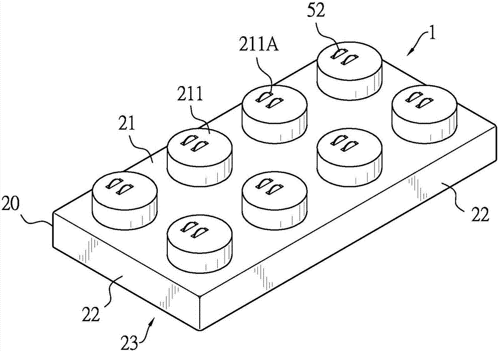
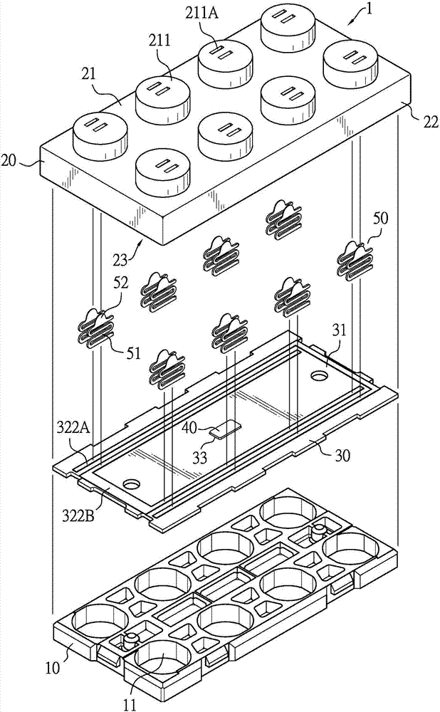
[0029] Such as figure 1 and figure 2 As shown, the conductive building block 1 of the present invention includes: a base 10 , a top cover 20 , a conductive plate 30 , a light emitting diode 40 and a plurality of electrical connectors 50 . The base 10 is a rectangular faceplate structure, and eight wedge holes 11 are pierced on the base 10 , the eight wedge holes 11 are respectively arranged in two parallel rows, and each row has four wedge holes 11 .

[0030] The top cover 20 is a hollow light-transmitting cover body, which has a top 21 and four ring side parts 22, and forms an accommodating space 23 inside the top cover 20 surrounded by the top 21 and the four ring side parts 22, And the accommodating space 23 is further provided with the aforementioned base 10 . The base 10 is installed on th...


PUM


Abstract

The invention discloses a conducting building block, which comprises a base, a top cover, a conducting plate, at least one electronic assembly and a plurality of electric connecting elements. The conducting building block is mainly characterized in that the contact mode of the plurality of electric connecting elements and the conducting plate is improved, so that the plurality of electric connecting elements are respectively in independent contact with the conducting plate to respectively form circuit paths, so that the condition that the plurality of electric connecting elements lose the electric power transmission function at the same time since each electric connecting element is influenced by the damage of any one electric connecting element cannot occur; and the influence on the electric power transmission of the whole conducting building block when the single electric connecting element fails can be reduced to the minimum.

Description

technical field [0001] The invention relates to a conductive building block, in particular to a conductive building block in which failure or breakage of a single electrical connector does not affect the circuit transmission of the entire conductive building block and can achieve thinning of the building block volume. Background technique [0002] At present, the invention patent application with the Chinese patent publication number CN104587683A discloses a kind of highly light-transmitting light-emitting building blocks, such as Figure 8 As shown, it can be formed by stacking blocks of building blocks and connecting them to conduct electricity to form a specific light-emitting pattern, so that the stacking combination of high-transmittance light-emitting blocks can form a variety of luminous shapes. [0003] However, when the high light-transmitting light-emitting building blocks of the prior art are stacked on each other, the protruding part 91 and the circuit board 100 c...

Claims


Application Information

Patent Timeline
Patent Type & Authority Applications(China)
IPC IPC(8): A63H33/12A63H33/26A63F9/12A63H33/22
CPCA63F9/1204A63F9/1208A63H33/042A63H33/105A63H33/108A63H33/12A63H33/22A63H33/26
Inventor 林嘉彦封亚平
Owner LONGMEN GETMORE POLYURETHANE
Why Eureka
Try Eureka