
Motor module

A technology of motors and printed circuit boards, applied in the field of motor modules, can solve the problems of difficult modularization and thinning, and difficult assembly of circuits and motor systems, so as to improve the qualified rate, improve the efficiency of motor assembly, and reduce the number of motor parts Effect

Active Publication Date: 2008-07-02
METAL INDS RES & DEV CENT
View PDF0 Cites 1 Cited by
  • Summary
  • Abstract
  • Description
  • Claims
  • Application Information

AI Technical Summary

Problems solved by technology

[0006] In view of the above-mentioned problems in the prior art, the present invention is a motor module electroplating surface treatment device, which is used to improve the disadvantages of difficult assembly of the circuit and motor system of the circuit board, and also overcome the disadvantages of difficulty in modularization and thinning

Method used


Image

  • Motor module
  • Motor module
  • Motor module

Examples


Embodiment Construction

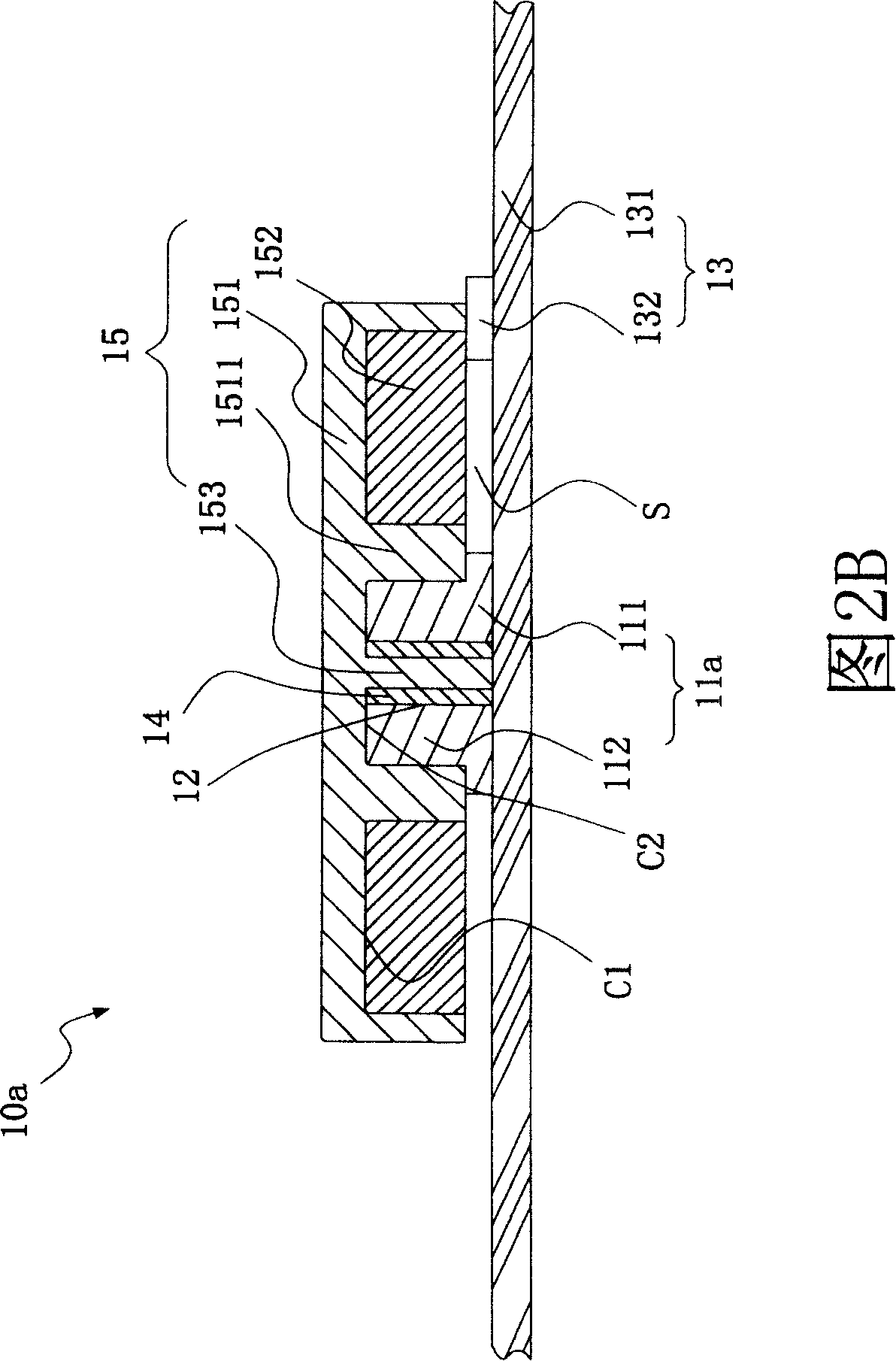
[0044] Please refer to Fig. 2A and Fig. 2B, a motor module of the present invention, the first embodiment of the motor module 10a includes a seat 11a, a set of holes 12, an electrical unit 13, a bearing 14 and a magnetic rotor unit 15 , the seat 11a has a supporting plate 111, and one end of the supporting plate 111 is extended with a set portion 112, and the set hole 12 runs through the above set portion 112, and extends through the supporting plate 111 for later description In other applications, the sleeve hole 12 can also be a stepped through hole, which runs through the sleeve part 112 and the bearing plate 111 at the same time, for the bearing 14 described later to be installed. Furthermore, the electrical unit 13 includes a printed circuit board 131 and several inductive components 132, the above-mentioned seat 11a is stacked on the printed circuit board 131, wherein the printed circuit board 131 forms a signal circuit 134 and a motor winding 135 by way of wiring, and th...


PUM


Abstract

The invention provides a motor module, which comprises a bearing pedestal with a bearing plate, a sleeve hole, an electric unit, a bearing sleeved with the sleeve hole and a magnetic rotator unit stacked and arranged on the bearing. A sleeve part is extended from the bearing and the sleeve holes are penetrated to allow the bearing to be sleeved with the sleeve part; the electric unit includes a printed circuit board and a plurality of induction components; wherein, the printed circuit board is wired to form a signal circuit and a motor winding; the induction components are arranged around the motor winding; the magnetic rotator unit is also arranged on the motor winding and a gap is kept between the electric rotator unit and the printed circuit board so that when the current is conducted in the motor winding, a magnetic inter-linkage induction is generated by the magnetic rotator unit and the motor winding to drive the magnetic rotator unit to rotate corresponding to the printed circuit board.

Description

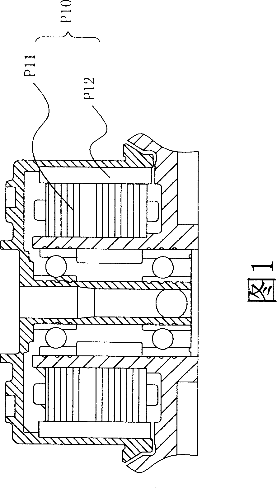
technical field [0001] The invention relates to a motor module, in particular to a motor module which is convenient for modular assembly and thinning and miniaturization. Background technique [0002] The currently widely used micro-motor modules include two parts: the motor system and the drive circuit board. Most of these micro-motor modules are assembled with the motor system first, and then pull out the reserved signal lines and power lines. , and subsequently connected with the above-mentioned drive circuit board, and then can drive the motor system of the micro motor module to run, so that the components to be driven can be driven by the motor system. [0003] However, the motor system part of the above-mentioned micro motor module is still too complicated or the volume cannot be miniaturized. Please refer to FIG. , causing the motor system P10 to rotate, and its stator winding P11 is still mostly manufactured by mechanical automation, so the factor of its manufacturi...

Claims


Application Information

Patent Timeline
Patent Type & Authority Applications(China)
IPC IPC(8): H02K21/24H02K29/08H02K3/00H02K1/27H02P6/16H05K3/10H02K5/16H02K5/04
Inventor 蔡明钦黄广淼黄建钦许良伊蔡明祺
Owner METAL INDS RES & DEV CENT
Learn More